Checking The Proportioning Valve And Metering Valve
Fragment manuala — str. 246
📋 Tekst do skopiowania / wyszukiwania
ABS (ANTI-LOCK BRAKE SYSTEM)
a
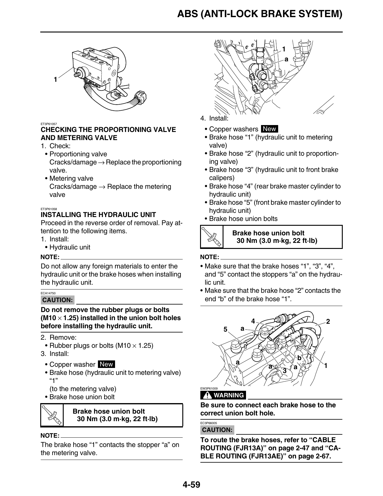
4. Install:
ET3P61057
CHECKING THE PROPORTIONING VALVE • Copper washers New
AND METERING VALVE • Brake hose “1” (hydraulic unit to metering
1. Check: valve)
• Proportioning valve • Brake hose “2” (hydraulic unit to proportion-
Cracks/damage → Replace the proportioning ing valve)
valve. • Brake hose “3” (hydraulic unit to front brake
• Metering valve calipers)
Cracks/damage → Replace the metering • Brake hose “4” (rear brake master cylinder to
valve hydraulic unit)
• Brake hose “5” (front brake master cylinder to
ET3P61058
hydraulic unit)
INSTALLING THE HYDRAULIC UNIT
• Brake hose union bolts
Proceed in the reverse order of removal. Pay at-
tention to the following items. Brake hose union bolt
1. Install: T.
R.
30 Nm (3.0 m·kg, 22 ft·lb)
• Hydraulic unit
NOTE: NOTE:
Do not allow any foreign materials to enter the • Make sure that the brake hoses “1”, “3”, “4”,
hydraulic unit or the brake hoses when installing and “5” contact the stoppers “a” on the hydrau-
the hydraulic unit. lic unit.
ECA14750 • Make sure that the brake hose “2” contacts the
CAUTION: end “b” of the brake hose “1”.
Do not remove the rubber plugs or bolts
(M10 × 1.25) installed in the union bolt holes 4 2
before installing the hydraulic unit. 5 a
2. Remove:
• Rubber plugs or bolts (M10 × 1.25)
3. Install:
b
• Copper washer New a
a a 1
• Brake hose (hydraulic unit to metering valve) 3
“1”
(to the metering valve) EW3P61009
• Brake hose union bolt WARNING
Be sure to connect each brake hose to the
Brake hose union bolt correct union bolt hole.
T.
R.
30 Nm (3.0 m·kg, 22 ft·lb) EC3P66005
CAUTION:
NOTE:
To route the brake hoses, refer to “CABLE
The brake hose “1” contacts the stopper “a” on ROUTING (FJR13A)” on page 2-47 and “CA-
the metering valve. BLE ROUTING (FJR13AE)” on page 2-67.
4-59