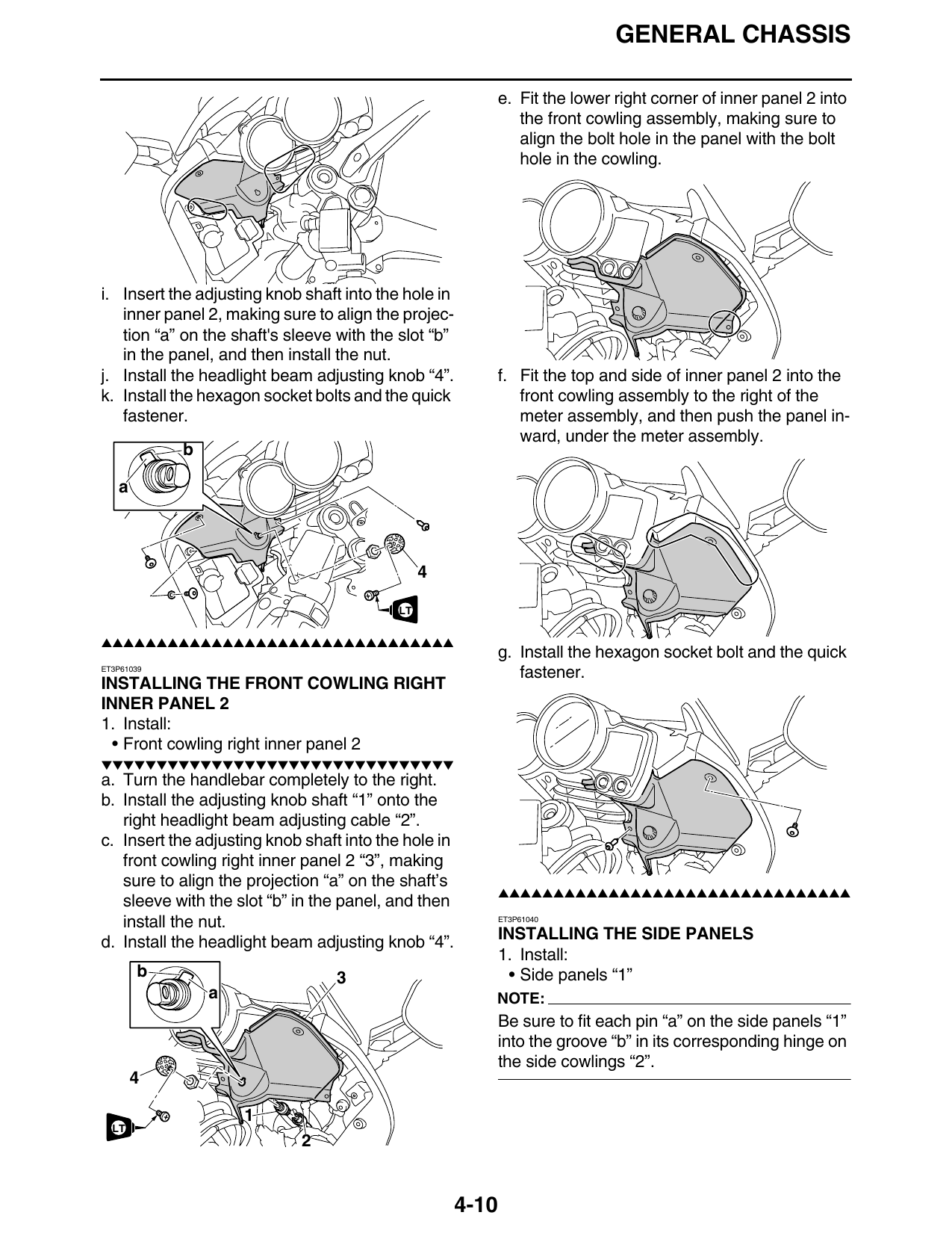
Installing The Front Cowling Right Inner Panel 2
Fragment manuala — str. 197–203
📋 Tekst do skopiowania / wyszukiwania
GENERAL CHASSIS
e. Fit the lower right corner of inner panel 2 into
the front cowling assembly, making sure to
align the bolt hole in the panel with the bolt
hole in the cowling.
i. Insert the adjusting knob shaft into the hole in
inner panel 2, making sure to align the projec-
tion “a” on the shaft's sleeve with the slot “b”
in the panel, and then install the nut.
j. Install the headlight beam adjusting knob “4”. f. Fit the top and side of inner panel 2 into the
k. Install the hexagon socket bolts and the quick front cowling assembly to the right of the
fastener. meter assembly, and then push the panel in-
ward, under the meter assembly.
b
a
LT
LT
▲▲▲▲▲▲▲▲▲▲▲▲▲▲▲▲▲▲▲▲▲▲▲▲▲▲▲▲▲▲▲▲
g. Install the hexagon socket bolt and the quick
ET3P61039
fastener.
INSTALLING THE FRONT COWLING RIGHT
INNER PANEL 2
1. Install:
• Front cowling right inner panel 2
▼▼▼▼▼▼▼▼▼▼▼▼▼▼▼▼▼▼▼▼▼▼▼▼▼▼▼▼▼▼▼▼
a. Turn the handlebar completely to the right.
b. Install the adjusting knob shaft “1” onto the
right headlight beam adjusting cable “2”.
c. Insert the adjusting knob shaft into the hole in
front cowling right inner panel 2 “3”, making
sure to align the projection “a” on the shaft’s
▲▲▲▲▲▲▲▲▲▲▲▲▲▲▲▲▲▲▲▲▲▲▲▲▲▲▲▲▲▲▲▲
sleeve with the slot “b” in the panel, and then
install the nut. ET3P61040
d. Install the headlight beam adjusting knob “4”. INSTALLING THE SIDE PANELS
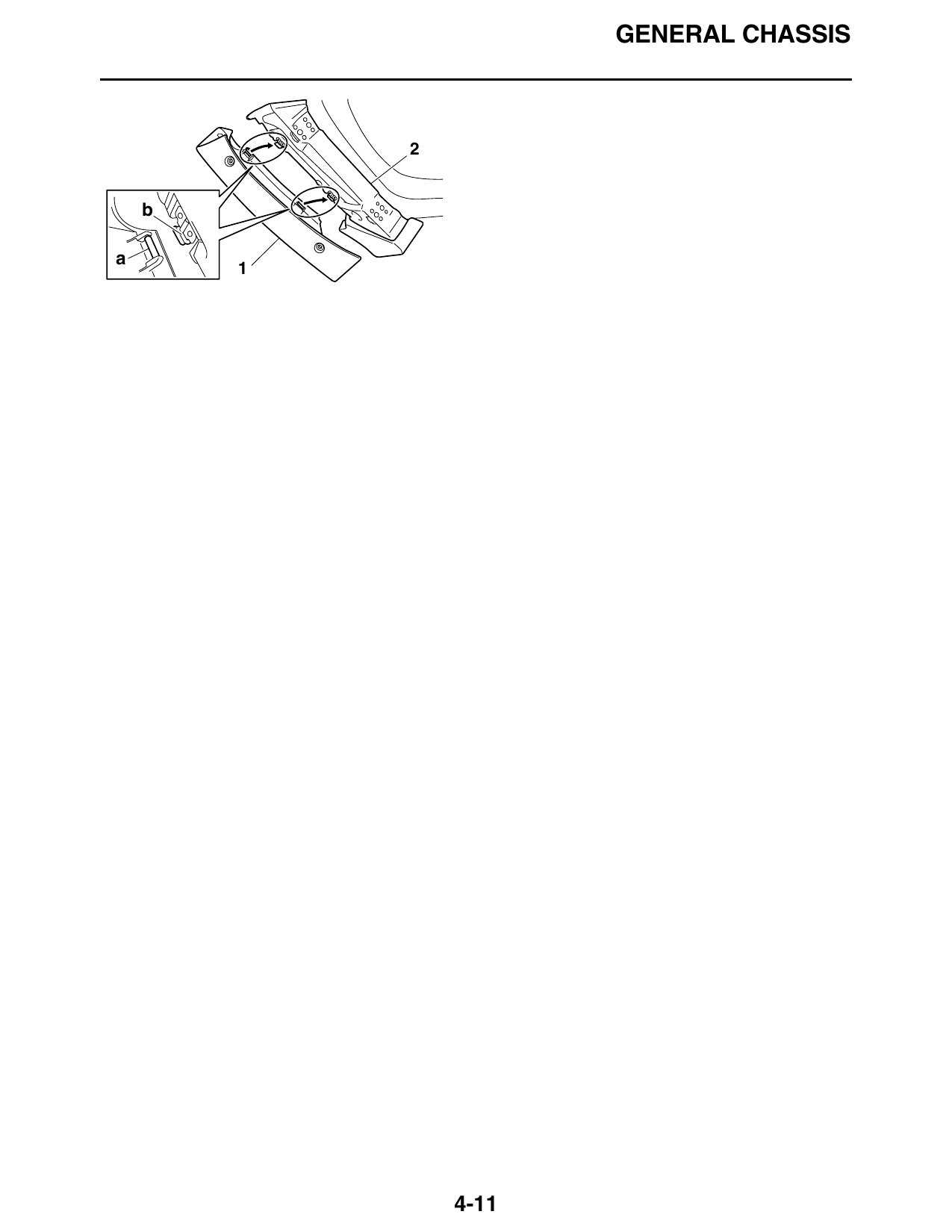
1. Install:
b 3 • Side panels “1”
a NOTE:
Be sure to fit each pin “a” on the side panels “1”
into the groove “b” in its corresponding hinge on
the side cowlings “2”.
LT
4-10
GENERAL CHASSIS
b
a
4-11
GENERAL CHASSIS
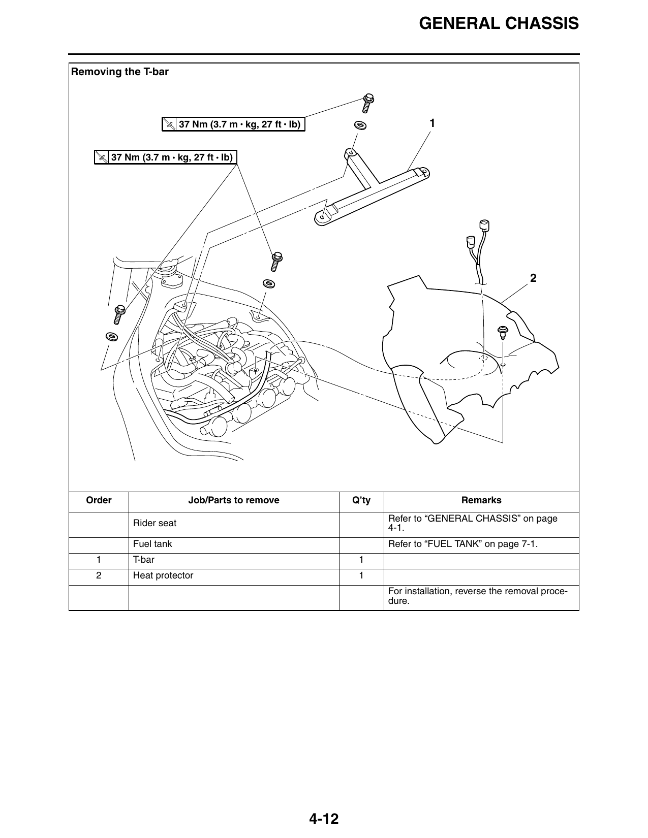
Removing the T-bar
T.
R.
37 Nm (3.7 m • kg, 27 ft • Ib) 1
T.
R.
37 Nm (3.7 m • kg, 27 ft • Ib)
Order Job/Parts to remove Q’ty Remarks
Refer to “GENERAL CHASSIS” on page
Rider seat 4-1.
Fuel tank Refer to “FUEL TANK” on page 7-1.
1 T-bar 1
2 Heat protector 1
For installation, reverse the removal proce-
dure.
4-12
GENERAL CHASSIS
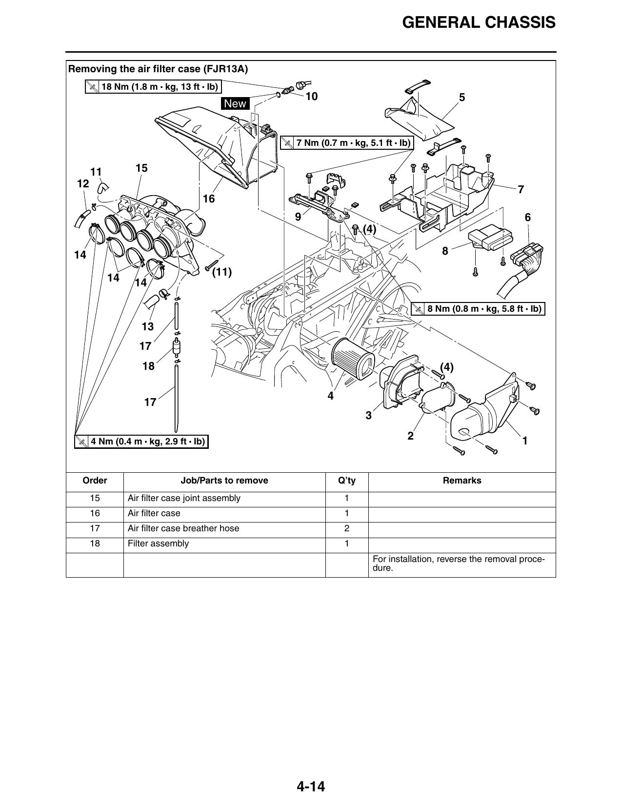
Removing the air filter case (FJR13A)
T.
R.
18 Nm (1.8 m • kg, 13 ft • Ib)
10 5
New
T.
R.
7 Nm (0.7 m • kg, 5.1 ft • Ib)
11 15
9 6
(4)
14 8
(11)
14 14
T.
R.
8 Nm (0.8 m • kg, 5.8 ft • Ib)
18 (4)
T. 4 Nm (0.4 m • kg, 2.9 ft • Ib)
2 1
R.
Order Job/Parts to remove Q’ty Remarks
Refer to “GENERAL CHASSIS” on page
Left side cover/T-bar 4-1.
Fuel tank Refer to “FUEL TANK” on page 7-1.
1 Air shroud 1
2 Air duct 1
3 Air filter case cover 1
4 Air filter element 1
5 Tool kit 1
6 ECU coupler 1 Disconnect.
7 Storage compartment 1
8 ECU (engine control unit) 1
9 Rear lower fuel tank bracket 1
10 Intake air temperature sensor 1
11 Bypass air unit inlet hose 1 Disconnect.
12 Crankcase breather hose 1 Disconnect.
Air induction system hose (air filter case joint
13 1 Disconnect.
assembly to 3-way joint)
14 Air filter case joint clamp screw 4 Loosen.
4-13
GENERAL CHASSIS
Removing the air filter case (FJR13A)
T.
R.
18 Nm (1.8 m • kg, 13 ft • Ib)
10 5
New
T.
R.
7 Nm (0.7 m • kg, 5.1 ft • Ib)
11 15
9 6
(4)
14 8
(11)
14 14
T.
R.
8 Nm (0.8 m • kg, 5.8 ft • Ib)
18 (4)
T. 4 Nm (0.4 m • kg, 2.9 ft • Ib)
2 1
R.
Order Job/Parts to remove Q’ty Remarks
15 Air filter case joint assembly 1
16 Air filter case 1
17 Air filter case breather hose 2
18 Filter assembly 1
For installation, reverse the removal proce-
dure.
4-14
GENERAL CHASSIS
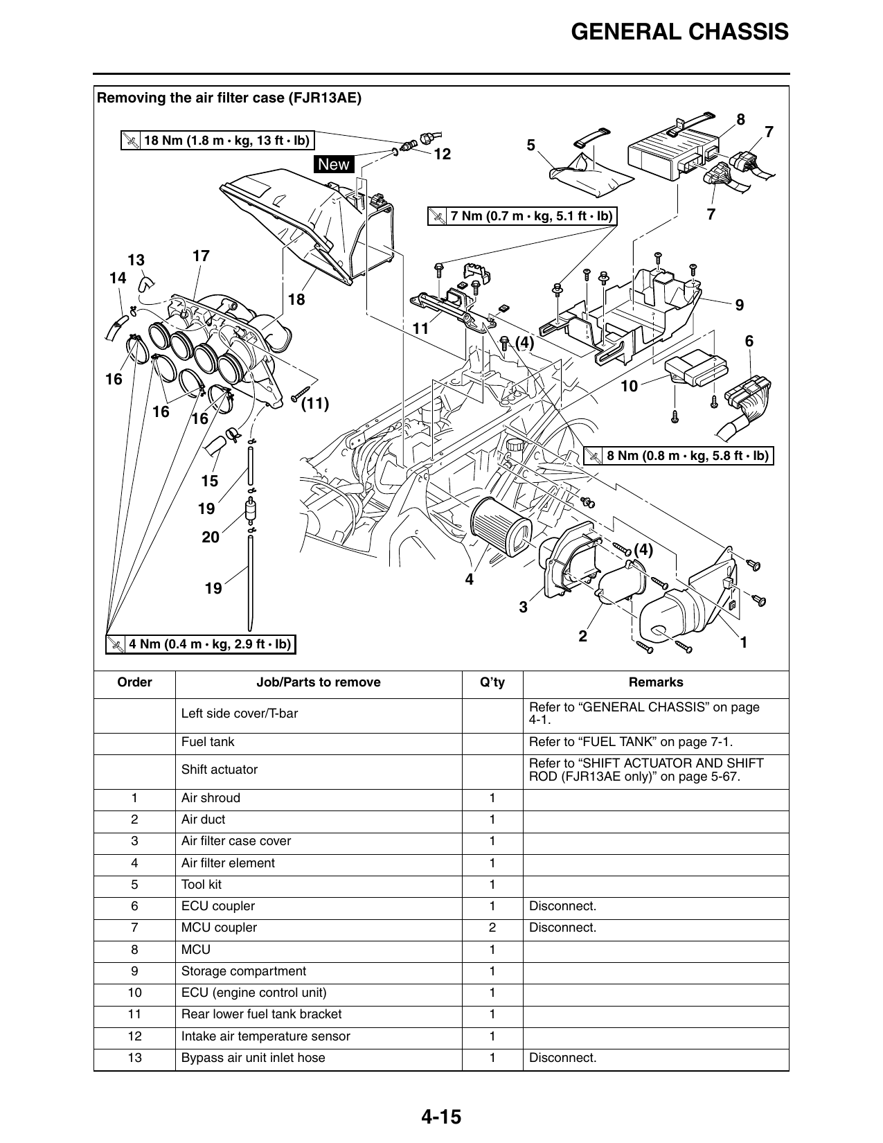
Removing the air filter case (FJR13AE)
18 Nm (1.8 m • kg, 13 ft • Ib)
T.
R.
New
T.
R.
7 Nm (0.7 m • kg, 5.1 ft • Ib) 7
13 17
18 9
(4) 6
16 10
(11)
16 16
T.
R.
8 Nm (0.8 m • kg, 5.8 ft • Ib)
(4)
T. 4 Nm (0.4 m • kg, 2.9 ft • Ib)
2 1
R.
Order Job/Parts to remove Q’ty Remarks
Refer to “GENERAL CHASSIS” on page
Left side cover/T-bar 4-1.
Fuel tank Refer to “FUEL TANK” on page 7-1.
Refer to “SHIFT ACTUATOR AND SHIFT
Shift actuator ROD (FJR13AE only)” on page 5-67.
1 Air shroud 1
2 Air duct 1
3 Air filter case cover 1
4 Air filter element 1
5 Tool kit 1
6 ECU coupler 1 Disconnect.
7 MCU coupler 2 Disconnect.
8 MCU 1
9 Storage compartment 1
10 ECU (engine control unit) 1
11 Rear lower fuel tank bracket 1
12 Intake air temperature sensor 1
13 Bypass air unit inlet hose 1 Disconnect.
4-15
GENERAL CHASSIS
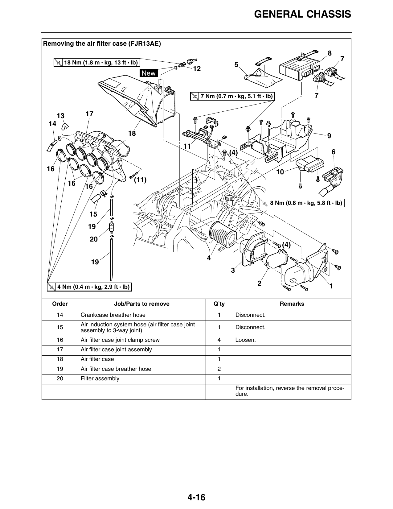
Removing the air filter case (FJR13AE)
18 Nm (1.8 m • kg, 13 ft • Ib)
T.
R.
New
T.
R.
7 Nm (0.7 m • kg, 5.1 ft • Ib) 7
13 17
18 9
(4) 6
16 10
(11)
16 16
T.
R.
8 Nm (0.8 m • kg, 5.8 ft • Ib)
(4)
T. 4 Nm (0.4 m • kg, 2.9 ft • Ib)
2 1
R.
Order Job/Parts to remove Q’ty Remarks
14 Crankcase breather hose 1 Disconnect.
Air induction system hose (air filter case joint
15 1 Disconnect.
assembly to 3-way joint)
16 Air filter case joint clamp screw 4 Loosen.
17 Air filter case joint assembly 1
18 Air filter case 1
19 Air filter case breather hose 2
20 Filter assembly 1
For installation, reverse the removal proce-
dure.
4-16