Adjusting The Foot Shift Switch
Fragment manuala — str. 371
📋 Tekst do skopiowania / wyszukiwania
SHIFT ACTUATOR AND SHIFT ROD (FJR13AE only)
4. Adjust:
Shift pedal pivot bolt • Foot shift switch
T.
R.
16 Nm (1.6 m·kg, 11 ft·lb) Refer to “ADJUSTING THE FOOT SHIFT
LOCTITE® SWITCH” on page 5-70.
NOTE: ET3P66040
ADJUSTING THE FOOT SHIFT SWITCH
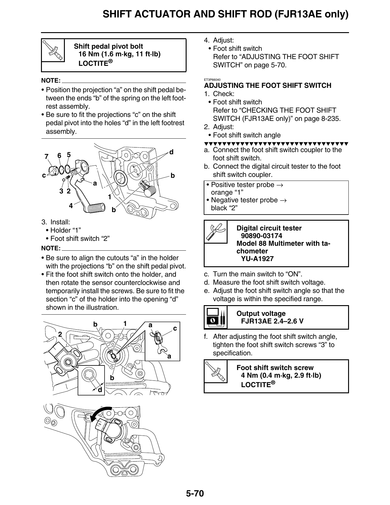
• Position the projection “a” on the shift pedal be-
1. Check:
tween the ends “b” of the spring on the left foot-
• Foot shift switch
rest assembly.
Refer to “CHECKING THE FOOT SHIFT
• Be sure to fit the projections “c” on the shift
SWITCH (FJR13AE only)” on page 8-235.
pedal pivot into the holes “d” in the left footrest
2. Adjust:
assembly.
• Foot shift switch angle
▼▼▼▼▼▼▼▼▼▼▼▼▼▼▼▼▼▼▼▼▼▼▼▼▼▼▼▼▼▼▼▼
d a. Connect the foot shift switch coupler to the
7 6 5 foot shift switch.
b. Connect the digital circuit tester to the foot
c b shift switch coupler.
a • Positive tester probe →
3 2 orange “1”
1 • Negative tester probe →
4 black “2”
b
3. Install:
• Holder “1” Digital circuit tester
• Foot shift switch “2” 90890-03174
Model 88 Multimeter with ta-
NOTE: chometer
• Be sure to align the cutouts “a” in the holder YU-A1927
with the projections “b” on the shift pedal pivot.
• Fit the foot shift switch onto the holder, and c. Turn the main switch to “ON”.
then rotate the sensor counterclockwise and d. Measure the foot shift switch voltage.
temporarily install the screws. Be sure to fit the e. Adjust the foot shift switch angle so that the
section “c” of the holder into the opening “d” voltage is within the specified range.
shown in the illustration.
Output voltage
b 1 FJR13AE 2.4–2.6 V
a c
2 f. After adjusting the foot shift switch angle,
tighten the foot shift switch screws “3” to
a specification.
Foot shift switch screw
b T.
R.
4 Nm (0.4 m·kg, 2.9 ft·lb)
LOCTITE®
d
5-70