Checking The Cylinders And Pistons
Fragment manuala — str. 406
📋 Tekst do skopiowania / wyszukiwania
CONNECTING RODS AND PISTONS
EAS26030
REMOVING THE CONNECTING RODS AND 1
PISTONS 4
The following procedure applies to all of the con-
necting rods and pistons. 3
1. Remove:
• Connecting rod cap “1” 2
NOTE: 1
Identify the position of each connecting rod so
that it can be reinstalled in its original place.
2. Remove: 4. Remove:
• Big end bearings • Top ring
(from the connecting rods and connecting rod • 2nd ring
caps) • Oil ring
NOTE: NOTE:
Identify the position of each big end bearing so When removing a piston ring, open the end gap
that it can be reinstalled in its original place. with your fingers and lift the other side of the ring
over the piston crown.
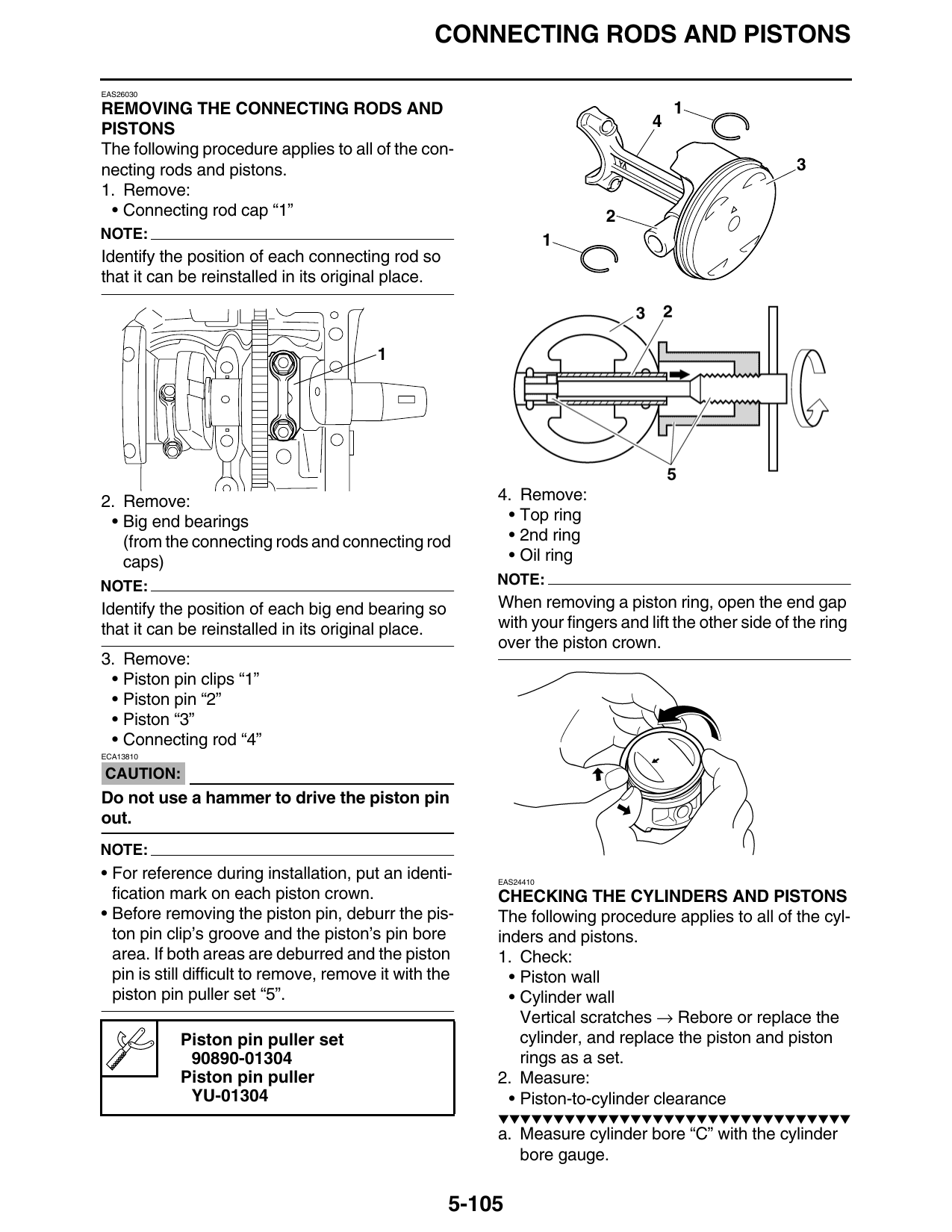
3. Remove:
• Piston pin clips “1”
• Piston pin “2”
• Piston “3”
• Connecting rod “4”
ECA13810
CAUTION:
Do not use a hammer to drive the piston pin
out.
NOTE:
• For reference during installation, put an identi- EAS24410
fication mark on each piston crown. CHECKING THE CYLINDERS AND PISTONS
• Before removing the piston pin, deburr the pis- The following procedure applies to all of the cyl-
ton pin clip’s groove and the piston’s pin bore inders and pistons.
area. If both areas are deburred and the piston 1. Check:
pin is still difficult to remove, remove it with the • Piston wall
piston pin puller set “5”. • Cylinder wall
Vertical scratches → Rebore or replace the
Piston pin puller set cylinder, and replace the piston and piston
90890-01304 rings as a set.
Piston pin puller 2. Measure:
YU-01304 • Piston-to-cylinder clearance
▼▼▼▼▼▼▼▼▼▼▼▼▼▼▼▼▼▼▼▼▼▼▼▼▼▼▼▼▼▼▼▼
a. Measure cylinder bore “C” with the cylinder
bore gauge.
5-105