Checking The Oil Delivery Pipes
Fragment manuala — str. 401–404
📋 Tekst do skopiowania / wyszukiwania
CRANKCASE
EAS25550 EAS25580
DISASSEMBLING THE CRANKCASE CHECKING THE CRANKCASE
1. Place the engine upside down. 1. Thoroughly wash the crankcase halves in a
2. Remove: mild solvent.
• Crankcase bolts 2. Thoroughly clean all the gasket surfaces and
NOTE: crankcase mating surfaces.
• Loosen each bolt 1/4 of a turn at a time, in stag- 3. Check:
es and in a crisscross pattern. After all of the • Crankcase
bolts are fully loosened, remove them. Cracks/damage → Replace.
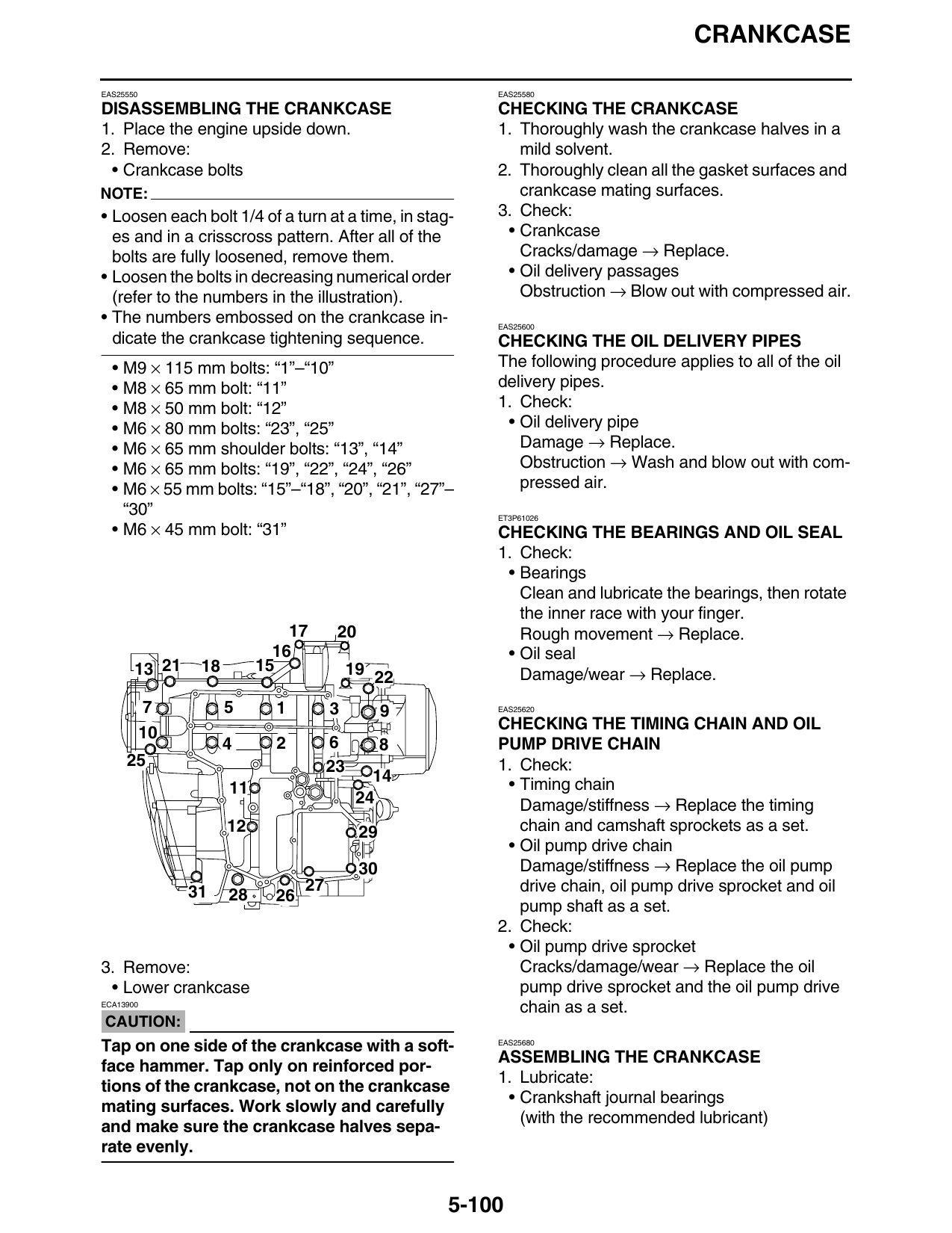
• Loosen the bolts in decreasing numerical order • Oil delivery passages
(refer to the numbers in the illustration). Obstruction → Blow out with compressed air.
• The numbers embossed on the crankcase in- EAS25600
dicate the crankcase tightening sequence. CHECKING THE OIL DELIVERY PIPES
• M9 × 115 mm bolts: “1”–“10” The following procedure applies to all of the oil
• M8 × 65 mm bolt: “11” delivery pipes.
• M8 × 50 mm bolt: “12” 1. Check:
• M6 × 80 mm bolts: “23”, “25” • Oil delivery pipe
• M6 × 65 mm shoulder bolts: “13”, “14” Damage → Replace.
• M6 × 65 mm bolts: “19”, “22”, “24”, “26” Obstruction → Wash and blow out with com-
• M6 × 55 mm bolts: “15”–“18”, “20”, “21”, “27”– pressed air.
“30” ET3P61026
• M6 × 45 mm bolt: “31” CHECKING THE BEARINGS AND OIL SEAL
1. Check:
• Bearings
Clean and lubricate the bearings, then rotate
the inner race with your finger.
17 20 Rough movement → Replace.
16 • Oil seal
13 21 18 15 19 22 Damage/wear → Replace.
7 5 1 3 9 EAS25620
CHECKING THE TIMING CHAIN AND OIL
4 2 6 8 PUMP DRIVE CHAIN
25 23 1. Check:
14 • Timing chain
24 Damage/stiffness → Replace the timing
12 29 chain and camshaft sprockets as a set.
• Oil pump drive chain
30 Damage/stiffness → Replace the oil pump
31 27 drive chain, oil pump drive sprocket and oil
28 26
pump shaft as a set.
2. Check:
• Oil pump drive sprocket
3. Remove: Cracks/damage/wear → Replace the oil
• Lower crankcase pump drive sprocket and the oil pump drive
ECA13900
chain as a set.
CAUTION:
Tap on one side of the crankcase with a soft- EAS25680
ASSEMBLING THE CRANKCASE
face hammer. Tap only on reinforced por-
1. Lubricate:
tions of the crankcase, not on the crankcase
• Crankshaft journal bearings
mating surfaces. Work slowly and carefully
(with the recommended lubricant)
and make sure the crankcase halves sepa-
rate evenly.
5-100
CRANKCASE
Recommended lubricant
Engine oil
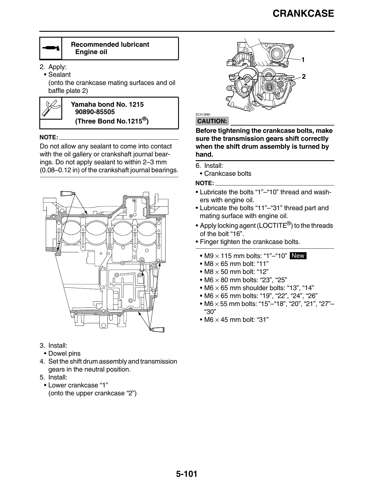
2. Apply:
• Sealant 2
(onto the crankcase mating surfaces and oil
baffle plate 2)
Yamaha bond No. 1215
90890-85505 ECA13980
(Three Bond No.1215®) CAUTION:
Before tightening the crankcase bolts, make
NOTE: sure the transmission gears shift correctly
Do not allow any sealant to come into contact when the shift drum assembly is turned by
with the oil gallery or crankshaft journal bear- hand.
ings. Do not apply sealant to within 2–3 mm
6. Install:
(0.08–0.12 in) of the crankshaft journal bearings.
• Crankcase bolts
NOTE:
• Lubricate the bolts “1”–“10” thread and wash-
ers with engine oil.
• Lubricate the bolts “11”–“31” thread part and
mating surface with engine oil.
• Apply locking agent (LOCTITE®) to the threads
of the bolt “16”.
• Finger tighten the crankcase bolts.
• M9 × 115 mm bolts: “1”–“10” New
• M8 × 65 mm bolt: “11”
• M8 × 50 mm bolt: “12”
• M6 × 80 mm bolts: “23”, “25”
• M6 × 65 mm shoulder bolts: “13”, “14”
• M6 × 65 mm bolts: “19”, “22”, “24”, “26”
• M6 × 55 mm bolts: “15”–“18”, “20”, “21”, “27”–
“30”
• M6 × 45 mm bolt: “31”
3. Install:
• Dowel pins
4. Set the shift drum assembly and transmission
gears in the neutral position.
5. Install:
• Lower crankcase “1”
(onto the upper crankcase “2”)
5-101
CRANKCASE
EW3P61014
WARNING
If the bolt is tightened more than the speci-
fied angle, do not loosen the bolt and then re-
17 20 tighten it. Instead, replace the bolt with a new
16 one and perform the procedure again.
13 21 18 15 19 22 EC3P61033
CAUTION:
7 5 1 3 9 • Do not use a torque wrench to tighten the
10 bolt to the specified angle.
4 2 6 8
25 • Tighten the bolt until it is at the specified
14 angle.
NOTE:
12 29 On a hexagonal bolt, note that the angle from
one corner to another is 60°.
31 27
28 26
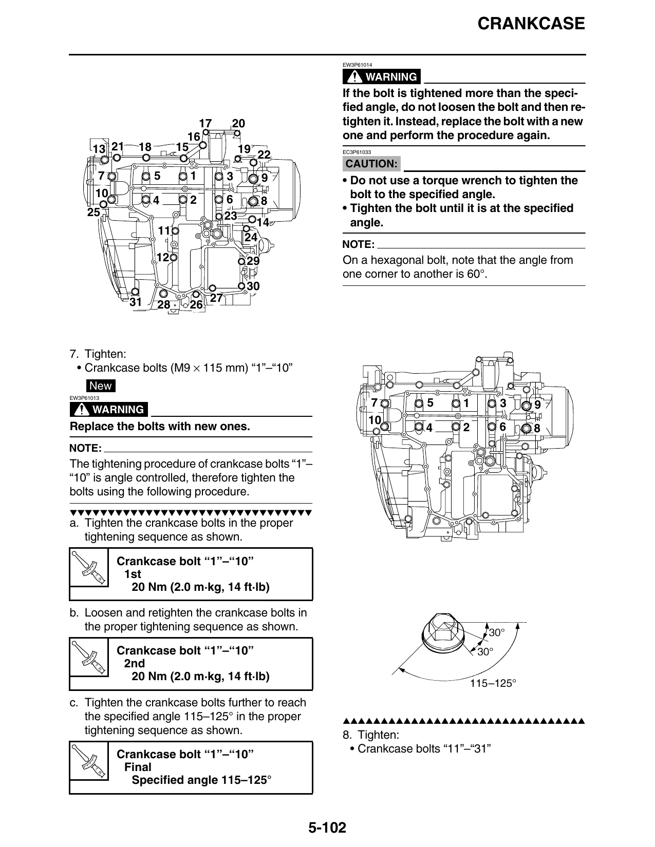
7. Tighten:
• Crankcase bolts (M9 × 115 mm) “1”–“10”
New
EW3P61013
7 5 1 3 9
WARNING
Replace the bolts with new ones. 4 2 6 8
NOTE:
The tightening procedure of crankcase bolts “1”–
“10” is angle controlled, therefore tighten the
bolts using the following procedure.
▼▼▼▼▼▼▼▼▼▼▼▼▼▼▼▼▼▼▼▼▼▼▼▼▼▼▼▼▼▼▼▼
a. Tighten the crankcase bolts in the proper
tightening sequence as shown.
Crankcase bolt “1”–“10”
T.
R.
1st
20 Nm (2.0 m·kg, 14 ft·lb)
b. Loosen and retighten the crankcase bolts in
the proper tightening sequence as shown.
Crankcase bolt “1”–“10”
T.
R.
2nd
20 Nm (2.0 m·kg, 14 ft·lb)
c. Tighten the crankcase bolts further to reach
the specified angle 115–125° in the proper ▲▲▲▲▲▲▲▲▲▲▲▲▲▲▲▲▲▲▲▲▲▲▲▲▲▲▲▲▲▲▲▲
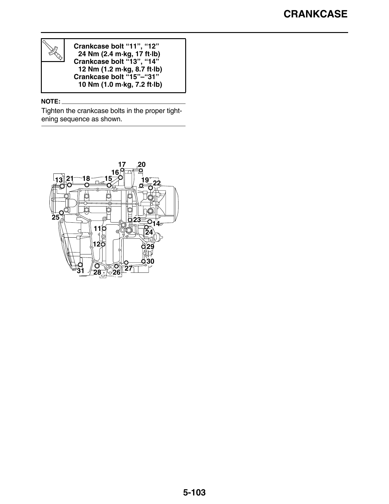
tightening sequence as shown. 8. Tighten:
Crankcase bolt “1”–“10” • Crankcase bolts “11”–“31”
T.
R.
Final
Specified angle 115–125°
5-102
CRANKCASE
Crankcase bolt “11”, “12”
T.
R.
24 Nm (2.4 m·kg, 17 ft·lb)
Crankcase bolt “13”, “14”
12 Nm (1.2 m·kg, 8.7 ft·lb)
Crankcase bolt “15”–“31”
10 Nm (1.0 m·kg, 7.2 ft·lb)
NOTE:
Tighten the crankcase bolts in the proper tight-
ening sequence as shown.
17 20
13 21 18 15 19 22
25 23
12 29
31 27
28 26
5-103