Checking The Valves And Valve Guides
Fragment manuala — str. 326–327
📋 Tekst do skopiowania / wyszukiwania
VALVES AND VALVE SPRINGS
EAS24280
REMOVING THE VALVES NOTE:
The following procedure applies to all of the Remove the valve cotters by compressing the
valves and related components. valve spring with the valve spring compressor
NOTE:
“1” and the valve spring compressor attachment
“2”.
Before removing the internal parts of the cylinder
head (e.g., valves, valve springs, valve seats),
make sure the valves properly seal. Valve spring compressor
90890-04019
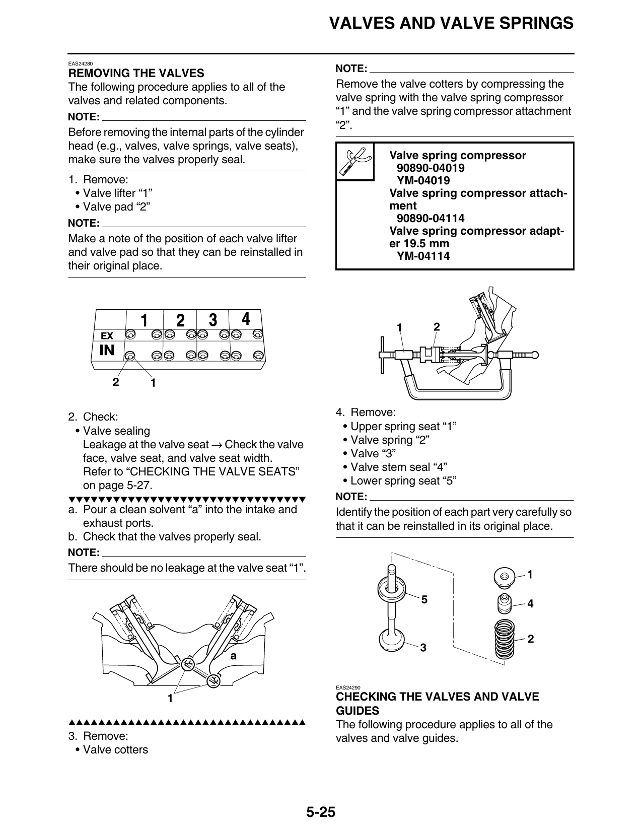
1. Remove: YM-04019
• Valve lifter “1” Valve spring compressor attach-
• Valve pad “2” ment
NOTE: 90890-04114
Valve spring compressor adapt-
Make a note of the position of each valve lifter er 19.5 mm
and valve pad so that they can be reinstalled in YM-04114
their original place.
2. Check: 4. Remove:
• Valve sealing • Upper spring seat “1”
Leakage at the valve seat → Check the valve • Valve spring “2”
face, valve seat, and valve seat width. • Valve “3”
Refer to “CHECKING THE VALVE SEATS” • Valve stem seal “4”
on page 5-27. • Lower spring seat “5”
▼▼▼▼▼▼▼▼▼▼▼▼▼▼▼▼▼▼▼▼▼▼▼▼▼▼▼▼▼▼▼▼ NOTE:
a. Pour a clean solvent “a” into the intake and Identify the position of each part very carefully so
exhaust ports. that it can be reinstalled in its original place.
b. Check that the valves properly seal.
NOTE:
There should be no leakage at the valve seat “1”.
EAS24290
CHECKING THE VALVES AND VALVE
GUIDES
▲▲▲▲▲▲▲▲▲▲▲▲▲▲▲▲▲▲▲▲▲▲▲▲▲▲▲▲▲▲▲▲ The following procedure applies to all of the
3. Remove: valves and valve guides.
• Valve cotters
5-25
VALVES AND VALVE SPRINGS
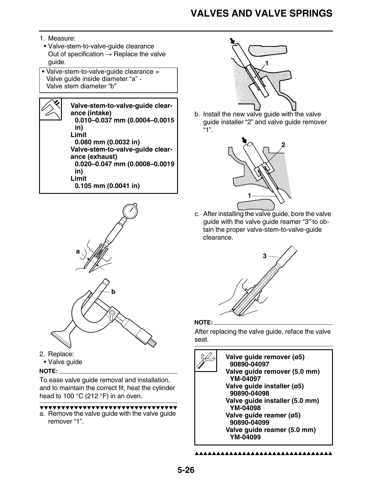
1. Measure:
• Valve-stem-to-valve-guide clearance
Out of specification → Replace the valve
guide.
• Valve-stem-to-valve-guide clearance =
Valve guide inside diameter “a” -
Valve stem diameter “b”
Valve-stem-to-valve-guide clear-
ance (intake) b. Install the new valve guide with the valve
0.010–0.037 mm (0.0004–0.0015 guide installer “2” and valve guide remover
in) “1”.
Limit
0.080 mm (0.0032 in)
Valve-stem-to-valve-guide clear-
ance (exhaust)
0.020–0.047 mm (0.0008–0.0019
in)
Limit
0.105 mm (0.0041 in)
c. After installing the valve guide, bore the valve
guide with the valve guide reamer “3” to ob-
tain the proper valve-stem-to-valve-guide
clearance.
NOTE:
After replacing the valve guide, reface the valve
seat.
2. Replace: Valve guide remover (ø5)
• Valve guide 90890-04097
NOTE: Valve guide remover (5.0 mm)
To ease valve guide removal and installation, YM-04097
and to maintain the correct fit, heat the cylinder Valve guide installer (ø5)
head to 100 °C (212 °F) in an oven. 90890-04098
Valve guide installer (5.0 mm)
▼▼▼▼▼▼▼▼▼▼▼▼▼▼▼▼▼▼▼▼▼▼▼▼▼▼▼▼▼▼▼▼ YM-04098
a. Remove the valve guide with the valve guide Valve guide reamer (ø5)
remover “1”. 90890-04099
Valve guide reamer (5.0 mm)
YM-04099
▲▲▲▲▲▲▲▲▲▲▲▲▲▲▲▲▲▲▲▲▲▲▲▲▲▲▲▲▲▲▲▲
5-26