🏍️ FJR1300 RP13

Installing The Gear Position Sensor (FJR13AE Only)

Fragment manuala — str. 312

📋 Tekst do skopiowania / wyszukiwania
ENGINE REMOVAL

ET3P66035
                                                             2. Adjust:
INSTALLING THE GEAR POSITION SENSOR
                                                              • Gear position sensor angle
(FJR13AE only)
                                                             ▼▼▼▼▼▼▼▼▼▼▼▼▼▼▼▼▼▼▼▼▼▼▼▼▼▼▼▼▼▼▼▼
1. Connect:                                                  a. Connect the gear position sensor coupler to
  • MCU coupler                                                  the gear position sensor.
  • ECU coupler                                              b. Connect the digital circuit tester to the gear
    Refer to “GENERAL CHASSIS” on page 4-1.                      position sensor.
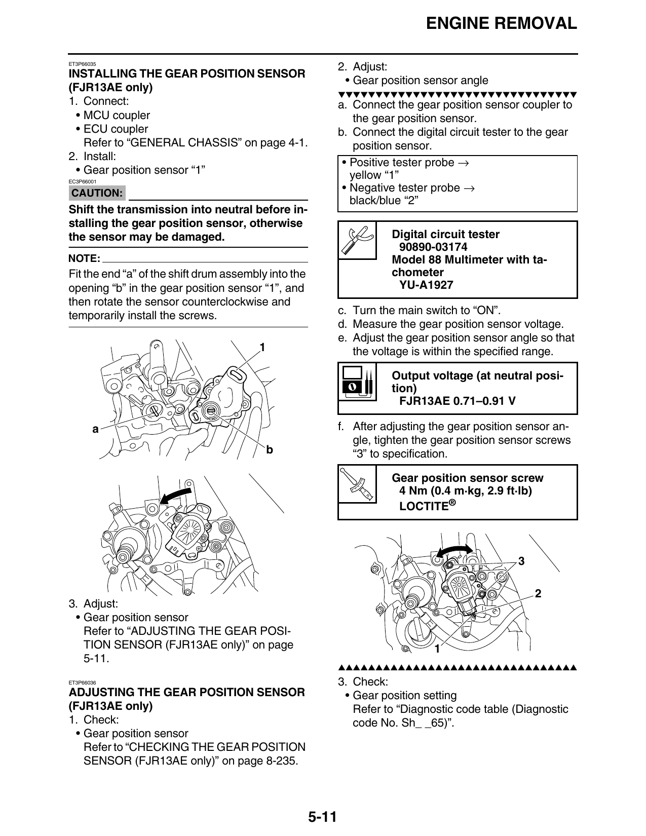
2. Install:
                                                              • Positive tester probe →
  • Gear position sensor “1”                                    yellow “1”
EC3P66001

CAUTION:                                                      • Negative tester probe →
                                                                black/blue “2”
Shift the transmission into neutral before in-
stalling the gear position sensor, otherwise
the sensor may be damaged.                                              Digital circuit tester
                                                                         90890-03174
NOTE:                                                                   Model 88 Multimeter with ta-
Fit the end “a” of the shift drum assembly into the                     chometer
opening “b” in the gear position sensor “1”, and                         YU-A1927
then rotate the sensor counterclockwise and
temporarily install the screws.                              c. Turn the main switch to “ON”.
                                                             d. Measure the gear position sensor voltage.
                                                             e. Adjust the gear position sensor angle so that
                                         1                      the voltage is within the specified range.

                                                                        Output voltage (at neutral posi-
                                                                        tion)
                                                                          FJR13AE 0.71–0.91 V

       a                                                     f. After adjusting the gear position sensor an-
                                                                gle, tighten the gear position sensor screws
                                             b                  “3” to specification.

                                                                        Gear position sensor screw
                                                                  T.
                                                                   R.
                                                                         4 Nm (0.4 m·kg, 2.9 ft·lb)
                                                                         LOCTITE®

3. Adjust:
 • Gear position sensor
   Refer to “ADJUSTING THE GEAR POSI-
   TION SENSOR (FJR13AE only)” on page                                           1
   5-11.
                                                             ▲▲▲▲▲▲▲▲▲▲▲▲▲▲▲▲▲▲▲▲▲▲▲▲▲▲▲▲▲▲▲▲
ET3P66036                                                    3. Check:
ADJUSTING THE GEAR POSITION SENSOR                            • Gear position setting
(FJR13AE only)                                                  Refer to “Diagnostic code table (Diagnostic
1. Check:                                                       code No. Sh_ _65)”.
  • Gear position sensor
    Refer to “CHECKING THE GEAR POSITION
    SENSOR (FJR13AE only)” on page 8-235.

                                                      5-11