Installing The Shift Shaft (FJR13A)
Fragment manuala — str. 375–376
📋 Tekst do skopiowania / wyszukiwania
SHIFT SHAFT
EAS25420
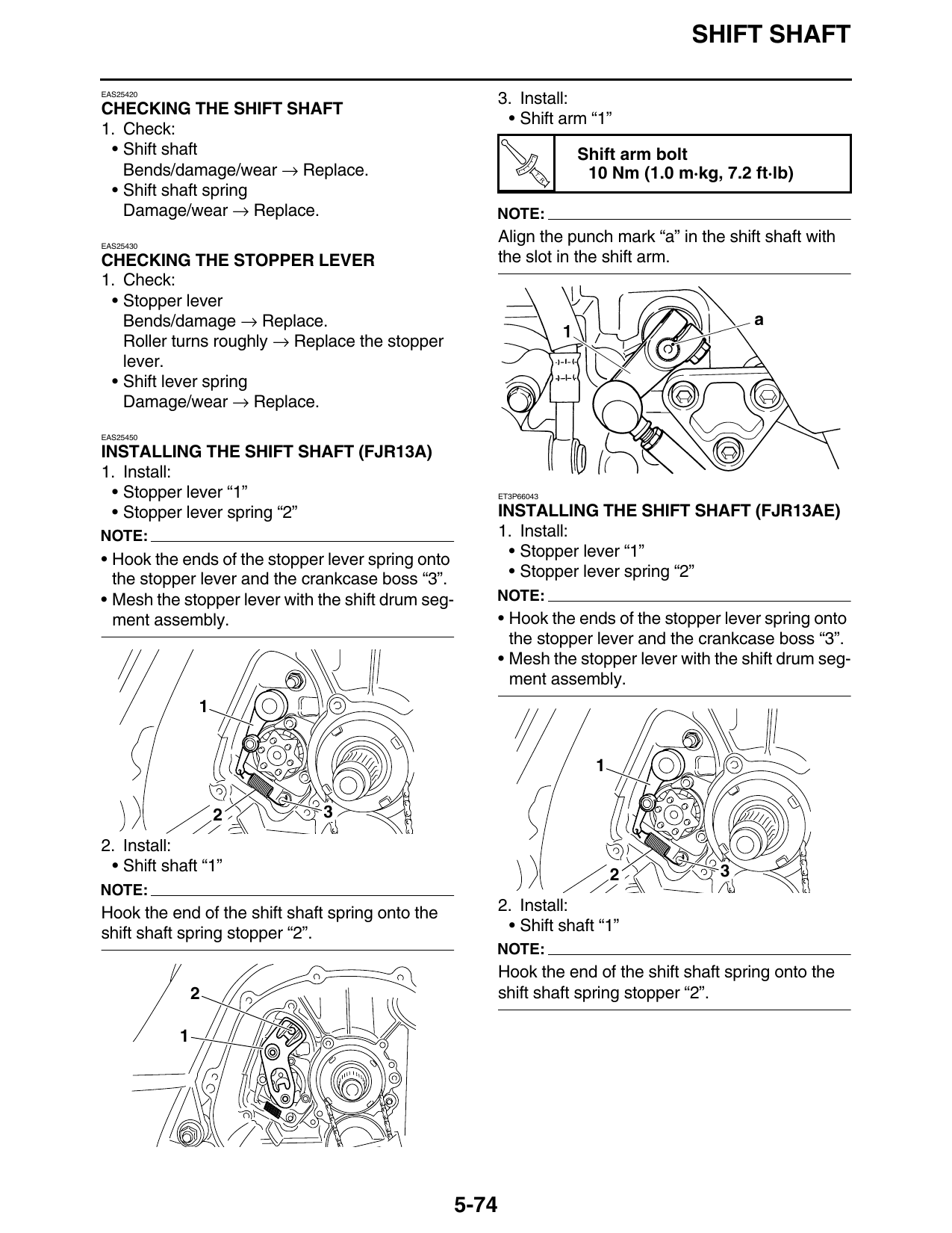
3. Install:
CHECKING THE SHIFT SHAFT
• Shift arm “1”
1. Check:
• Shift shaft Shift arm bolt
Bends/damage/wear → Replace. T.
R.
10 Nm (1.0 m·kg, 7.2 ft·lb)
• Shift shaft spring
Damage/wear → Replace. NOTE:
EAS25430
Align the punch mark “a” in the shift shaft with
CHECKING THE STOPPER LEVER the slot in the shift arm.
1. Check:
• Stopper lever
Bends/damage → Replace.
Roller turns roughly → Replace the stopper
lever.
• Shift lever spring
Damage/wear → Replace.
EAS25450
INSTALLING THE SHIFT SHAFT (FJR13A)
1. Install:
• Stopper lever “1” ET3P66043
• Stopper lever spring “2” INSTALLING THE SHIFT SHAFT (FJR13AE)
NOTE: 1. Install:
• Hook the ends of the stopper lever spring onto • Stopper lever “1”
the stopper lever and the crankcase boss “3”. • Stopper lever spring “2”
• Mesh the stopper lever with the shift drum seg- NOTE:
ment assembly. • Hook the ends of the stopper lever spring onto
the stopper lever and the crankcase boss “3”.
• Mesh the stopper lever with the shift drum seg-
ment assembly.
2 3
2. Install:
• Shift shaft “1” 3
NOTE:
Hook the end of the shift shaft spring onto the 2. Install:
shift shaft spring stopper “2”. • Shift shaft “1”
NOTE:
Hook the end of the shift shaft spring onto the
2 shift shaft spring stopper “2”.
5-74
SHIFT SHAFT
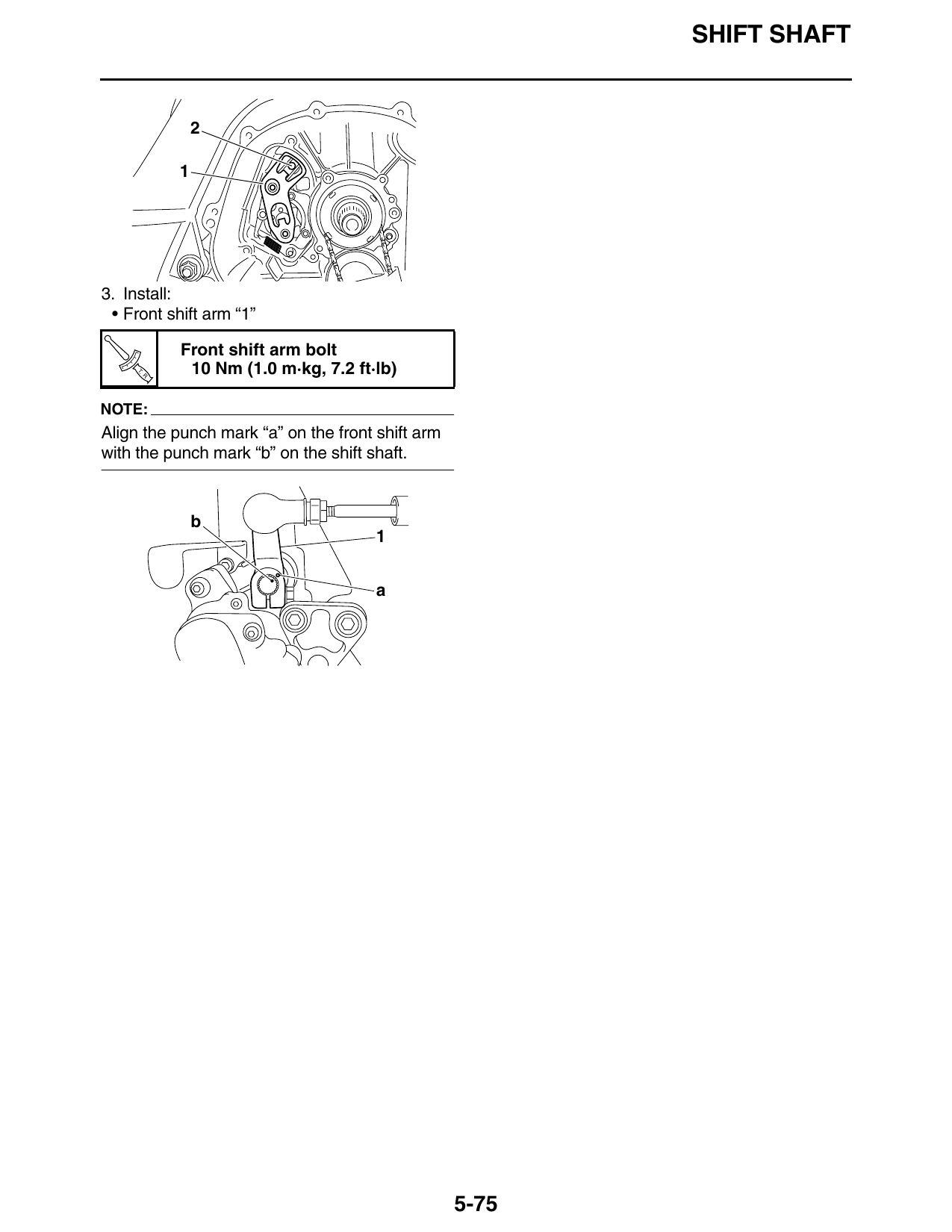
3. Install:
• Front shift arm “1”
Front shift arm bolt
T.
R.
10 Nm (1.0 m·kg, 7.2 ft·lb)
NOTE:
Align the punch mark “a” on the front shift arm
with the punch mark “b” on the shift shaft.
b
a
5-75