Air Induction System
Fragment manuala — str. 462–465
📋 Tekst do skopiowania / wyszukiwania
AIR INDUCTION SYSTEM
EAS27040
AIR INDUCTION SYSTEM
1 4 5 1
2 3
7 8
2 6
7-11
AIR INDUCTION SYSTEM
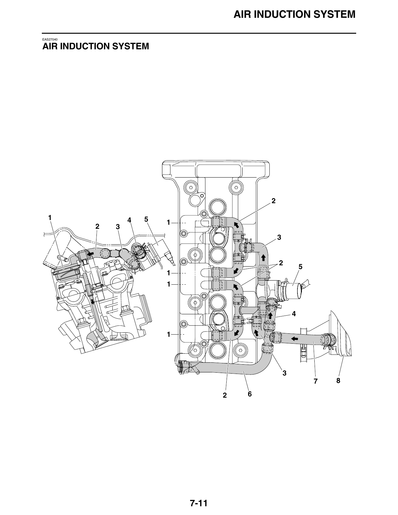
1. Reed valve assembly
2. Air induction system hose (3-way joint to reed
valve cover)
3. Air induction system hose (air cut-off valve to
3-way joint)
4. Air induction system hose (3-way joint to air
cut-off valve)
5. Air cut-off valve
6. Air induction system hose (3-way joint to hose
plug)
7. Air induction system hose (air filter case joint
assembly to 3-way joint)
8. Air filter case joint assembly
7-12
AIR INDUCTION SYSTEM
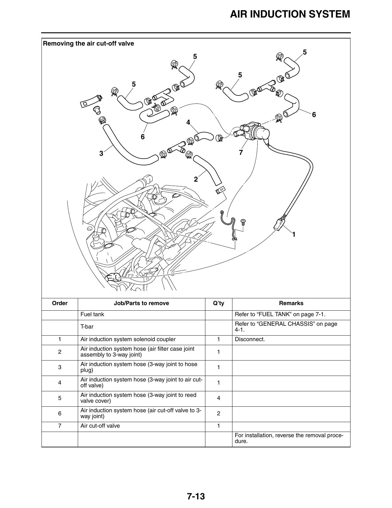
Removing the air cut-off valve
3 7
Order Job/Parts to remove Q’ty Remarks
Fuel tank Refer to “FUEL TANK” on page 7-1.
Refer to “GENERAL CHASSIS” on page
T-bar 4-1.
1 Air induction system solenoid coupler 1 Disconnect.
Air induction system hose (air filter case joint
2 1
assembly to 3-way joint)
Air induction system hose (3-way joint to hose
3 1
plug)
Air induction system hose (3-way joint to air cut-
4 1
off valve)
Air induction system hose (3-way joint to reed
5 4
valve cover)
Air induction system hose (air cut-off valve to 3-
6 2
way joint)
7 Air cut-off valve 1
For installation, reverse the removal proce-
dure.
7-13
AIR INDUCTION SYSTEM
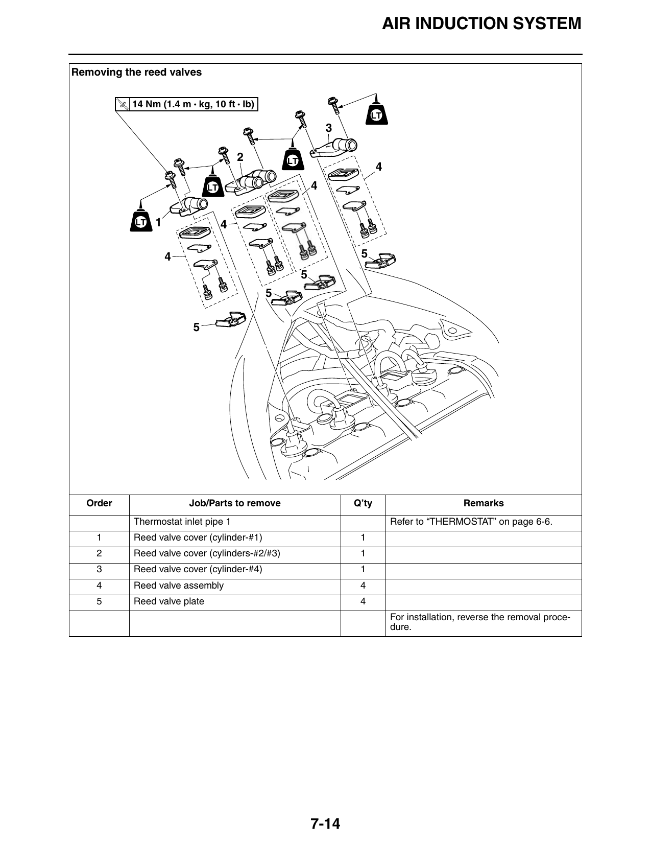
Removing the reed valves
T.
R.
14 Nm (1.4 m • kg, 10 ft • Ib)
LT
2 LT
LT 4
LT 1 4
4 5
Order Job/Parts to remove Q’ty Remarks
Thermostat inlet pipe 1 Refer to “THERMOSTAT” on page 6-6.
1 Reed valve cover (cylinder-#1) 1
2 Reed valve cover (cylinders-#2/#3) 1
3 Reed valve cover (cylinder-#4) 1
4 Reed valve assembly 4
5 Reed valve plate 4
For installation, reverse the removal proce-
dure.
7-14