Checking The Air Induction System
Fragment manuala — str. 466
📋 Tekst do skopiowania / wyszukiwania
AIR INDUCTION SYSTEM
EAS27050
1. Check:
CHECKING THE PRESSURE REGULATOR
• Hoses
1. Check:
Loose connections → Connect properly.
• Pressure regulator
Cracks/damage → Replace.
Damage → Replace.
• Pipes
EAS27060 Cracks/damage → Replace.
CHECKING THE AIR INDUCTION SYSTEM 2. Check:
• Reed valve
Air injection • Reed valve stopper
The air induction system burns unburned ex- • Reed valve seat
haust gases by injecting fresh air (secondary air) Cracks/damage → Replace the reed valve.
into the exhaust port, reducing the emission of 3. Check:
hydrocarbons. When there is negative pressure • Air cut-off valve
at the exhaust port, the reed valve opens, allow- Cracks/damage → Replace.
ing secondary air to flow into the exhaust port. 4. Check:
The required temperature for burning the un- • Air induction system solenoid
burned exhaust gases is approximately 600 to Refer to “CHECKING THE AIR INDUCTION
700 °C (1112 to 1292 °F). SYSTEM SOLENOID” on page 8-232.
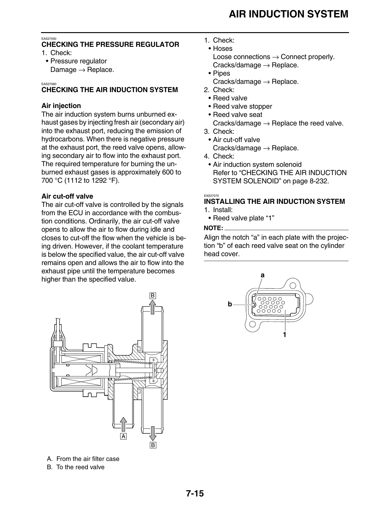
Air cut-off valve EAS27070
The air cut-off valve is controlled by the signals INSTALLING THE AIR INDUCTION SYSTEM
from the ECU in accordance with the combus- 1. Install:
tion conditions. Ordinarily, the air cut-off valve • Reed valve plate “1”
opens to allow the air to flow during idle and NOTE:
closes to cut-off the flow when the vehicle is be- Align the notch “a” in each plate with the projec-
ing driven. However, if the coolant temperature tion “b” of each reed valve seat on the cylinder
is below the specified value, the air cut-off valve head cover.
remains open and allows the air to flow into the
exhaust pipe until the temperature becomes
a
higher than the specified value.
B
b
A
B
A. From the air filter case
B. To the reed valve
7-15