Checking The Injectors
Fragment manuala — str. 459–461

📋 Tekst do skopiowania / wyszukiwania
THROTTLE BODIES
EAS26980
CHECKING THE INJECTORS Pressure gauge
1. Check: 90890-03153
• Injectors YU-03153
Damage → Replace. Fuel pressure adapter
90890-03176
EAS26990
YM-03176
CHECKING THE THROTTLE BODIES
1. Check:
• Throttle bodies 4
Cracks/damage → Replace the throttle bod-
ies as a set.
2. Check:
• Fuel passages 3
Obstructions → Clean.
▼▼▼▼▼▼▼▼▼▼▼▼▼▼▼▼▼▼▼▼▼▼▼▼▼▼▼▼▼▼▼▼
a. Wash the throttle bodies in a petroleum-
based solvent. 1 2
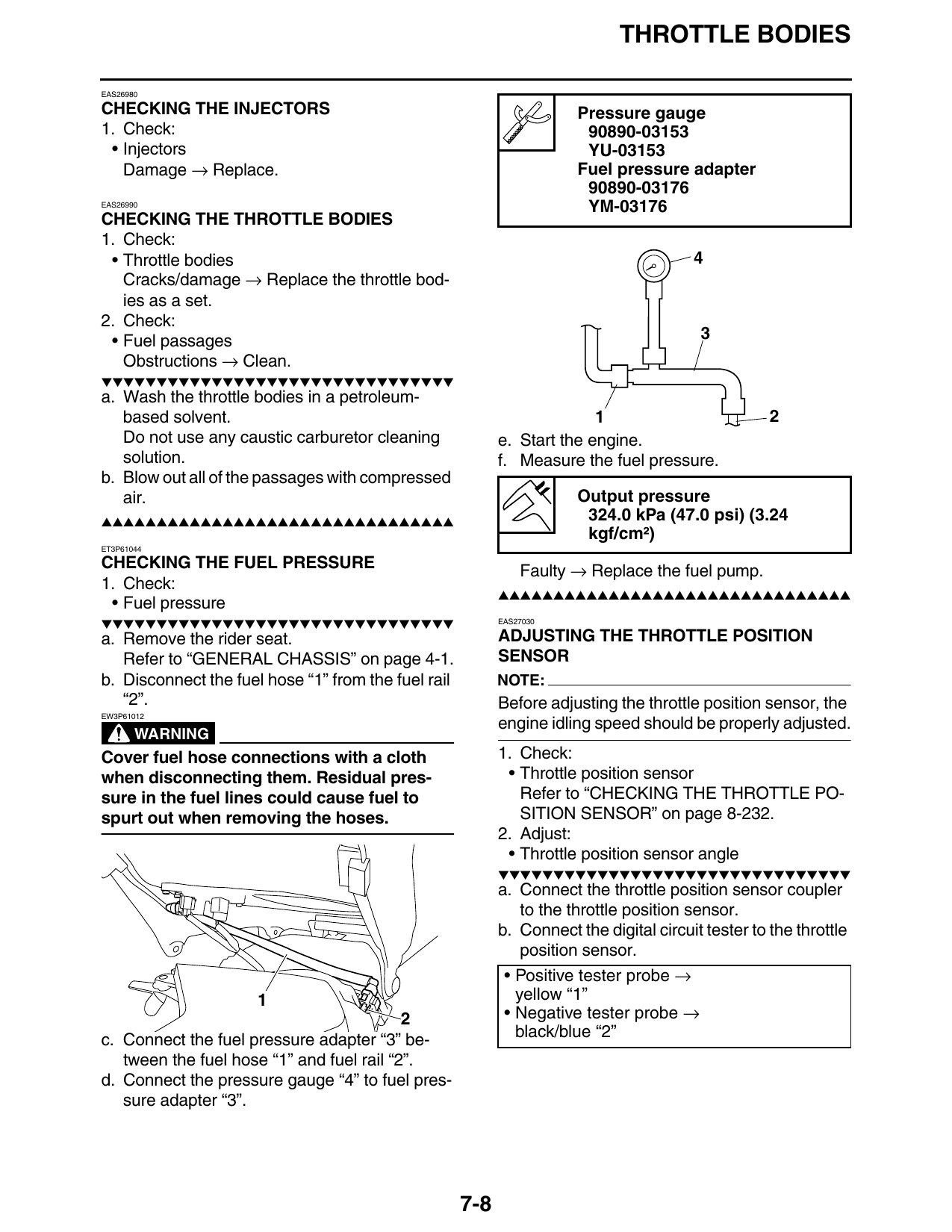
Do not use any caustic carburetor cleaning e. Start the engine.
solution. f. Measure the fuel pressure.
b. Blow out all of the passages with compressed
air. Output pressure
▲▲▲▲▲▲▲▲▲▲▲▲▲▲▲▲▲▲▲▲▲▲▲▲▲▲▲▲▲▲▲▲ 324.0 kPa (47.0 psi) (3.24
kgf/cm²)
ET3P61044
CHECKING THE FUEL PRESSURE Faulty → Replace the fuel pump.
1. Check:
▲▲▲▲▲▲▲▲▲▲▲▲▲▲▲▲▲▲▲▲▲▲▲▲▲▲▲▲▲▲▲▲
• Fuel pressure
▼▼▼▼▼▼▼▼▼▼▼▼▼▼▼▼▼▼▼▼▼▼▼▼▼▼▼▼▼▼▼▼ EAS27030
a. Remove the rider seat. ADJUSTING THE THROTTLE POSITION
Refer to “GENERAL CHASSIS” on page 4-1. SENSOR
b. Disconnect the fuel hose “1” from the fuel rail NOTE:
“2”. Before adjusting the throttle position sensor, the
EW3P61012
engine idling speed should be properly adjusted.
WARNING
Cover fuel hose connections with a cloth 1. Check:
when disconnecting them. Residual pres- • Throttle position sensor
sure in the fuel lines could cause fuel to Refer to “CHECKING THE THROTTLE PO-
spurt out when removing the hoses. SITION SENSOR” on page 8-232.
2. Adjust:
• Throttle position sensor angle
▼▼▼▼▼▼▼▼▼▼▼▼▼▼▼▼▼▼▼▼▼▼▼▼▼▼▼▼▼▼▼▼
a. Connect the throttle position sensor coupler
to the throttle position sensor.
b. Connect the digital circuit tester to the throttle
position sensor.
• Positive tester probe →
1 yellow “1”
2 • Negative tester probe →
c. Connect the fuel pressure adapter “3” be- black/blue “2”
tween the fuel hose “1” and fuel rail “2”.
d. Connect the pressure gauge “4” to fuel pres-
sure adapter “3”.
7-8
THROTTLE BODIES
Digital circuit tester
90890-03174
Model 88 Multimeter with ta-
chometer
YU-A1927
c. Turn the main switch to “ON”.
d. Measure the throttle position sensor voltage.
e. Adjust the throttle position sensor angle so
that the voltage is within the specified range.
Output voltage (at idle)
0.63–0.73 V
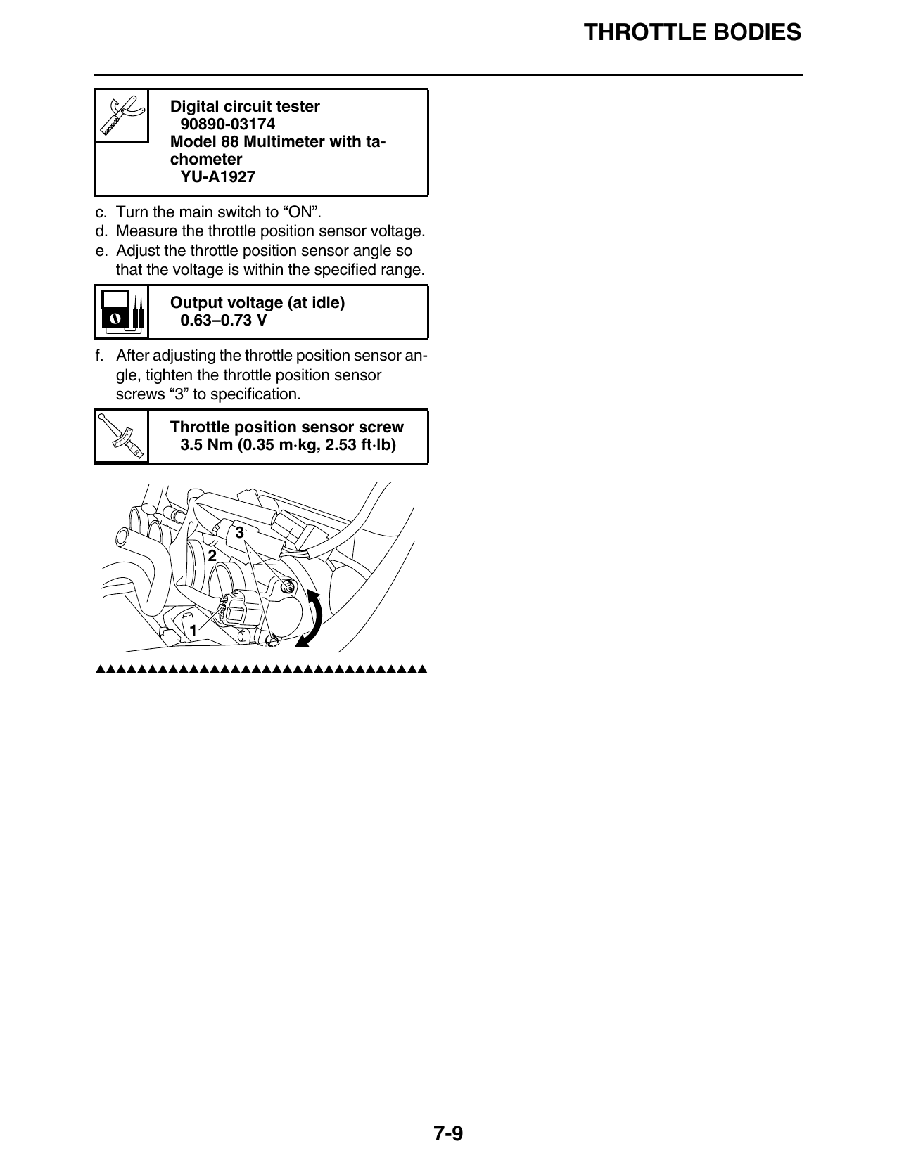
f. After adjusting the throttle position sensor an-
gle, tighten the throttle position sensor
screws “3” to specification.
Throttle position sensor screw
T.
R.
3.5 Nm (0.35 m·kg, 2.53 ft·lb)
▲▲▲▲▲▲▲▲▲▲▲▲▲▲▲▲▲▲▲▲▲▲▲▲▲▲▲▲▲▲▲▲
7-9
THROTTLE BODIES
7-10