Checking The Accessory Box Solenoid
Fragment manuala — str. 705
📋 Tekst do skopiowania / wyszukiwania
ELECTRICAL COMPONENTS
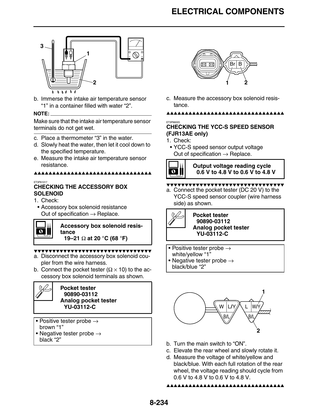
Br B
2 1 2
b. Immerse the intake air temperature sensor c. Measure the accessory box solenoid resis-
“1” in a container filled with water “2”. tance.
NOTE: ▲▲▲▲▲▲▲▲▲▲▲▲▲▲▲▲▲▲▲▲▲▲▲▲▲▲▲▲▲▲▲▲
Make sure that the intake air temperature sensor ET3P66020
terminals do not get wet. CHECKING THE YCC-S SPEED SENSOR
(FJR13AE only)
c. Place a thermometer “3” in the water. 1. Check:
d. Slowly heat the water, then let it cool down to • YCC-S speed sensor output voltage
the specified temperature. Out of specification → Replace.
e. Measure the intake air temperature sensor
resistance. Output voltage reading cycle
▲▲▲▲▲▲▲▲▲▲▲▲▲▲▲▲▲▲▲▲▲▲▲▲▲▲▲▲▲▲▲▲ 0.6 V to 4.8 V to 0.6 V to 4.8 V
ET3P61017
▼▼▼▼▼▼▼▼▼▼▼▼▼▼▼▼▼▼▼▼▼▼▼▼▼▼▼▼▼▼▼▼
CHECKING THE ACCESSORY BOX
a. Connect the pocket tester (DC 20 V) to the
SOLENOID
YCC-S speed sensor coupler (wire harness
1. Check:
side) as shown.
• Accessory box solenoid resistance
Out of specification → Replace. Pocket tester
90890-03112
Accessory box solenoid resis- Analog pocket tester
tance YU-03112-C
19–21 Ω at 20 °C (68 °F)
▼▼▼▼▼▼▼▼▼▼▼▼▼▼▼▼▼▼▼▼▼▼▼▼▼▼▼▼▼▼▼▼
• Positive tester probe →
a. Disconnect the accessory box solenoid cou- white/yellow “1”
pler from the wire harness. • Negative tester probe →
b. Connect the pocket tester (Ω × 10) to the ac- black/blue “2”
cessory box solenoid terminals as shown.
Pocket tester
90890-03112 1
Analog pocket tester
YU-03112-C W L/Y L W/Y
B/L B/L
• Positive tester probe →
brown “1”
• Negative tester probe → 2
black “2”
b. Turn the main switch to “ON”.
c. Elevate the rear wheel and slowly rotate it.
d. Measure the voltage of white/yellow and
black/blue. With each full rotation of the rear
wheel, the voltage reading should cycle from
0.6 V to 4.8 V to 0.6 V to 4.8 V.
▲▲▲▲▲▲▲▲▲▲▲▲▲▲▲▲▲▲▲▲▲▲▲▲▲▲▲▲▲▲▲▲
8-234