Checking The Crankshaft Position Sensor
Fragment manuala — str. 698
📋 Tekst do skopiowania / wyszukiwania
ELECTRICAL COMPONENTS
c. Measure the secondary coil resistance. 2. Check:
▲▲▲▲▲▲▲▲▲▲▲▲▲▲▲▲▲▲▲▲▲▲▲▲▲▲▲▲▲▲▲▲ • Crankshaft position sensor resistance
ET3P61015
Out of specification → Replace the crank-
CHECKING THE IGNITION SPARK GAP shaft position sensor.
1. Check:
Crankshaft position sensor resis-
• Ignition spark gap
tance
Out of specification → Perform the ignition 421–569 Ω at 20 °C (68 °F)
system troubleshooting, starting with step 5.
Refer to “TROUBLESHOOTING” on page ▼▼▼▼▼▼▼▼▼▼▼▼▼▼▼▼▼▼▼▼▼▼▼▼▼▼▼▼▼▼▼▼
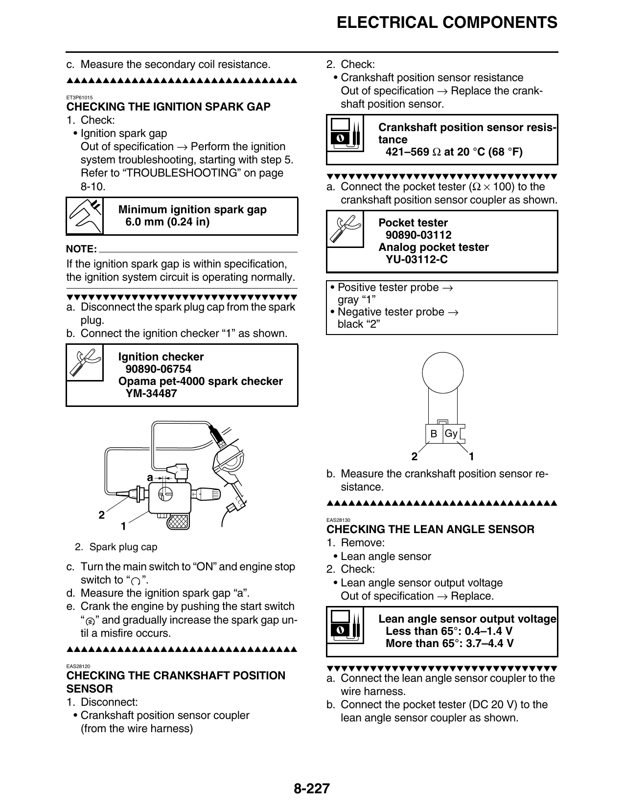
8-10. a. Connect the pocket tester (Ω × 100) to the
crankshaft position sensor coupler as shown.
Minimum ignition spark gap
6.0 mm (0.24 in) Pocket tester
90890-03112
NOTE: Analog pocket tester
If the ignition spark gap is within specification, YU-03112-C
the ignition system circuit is operating normally.
• Positive tester probe →
▼▼▼▼▼▼▼▼▼▼▼▼▼▼▼▼▼▼▼▼▼▼▼▼▼▼▼▼▼▼▼▼ gray “1”
a. Disconnect the spark plug cap from the spark • Negative tester probe →
plug. black “2”
b. Connect the ignition checker “1” as shown.
Ignition checker
90890-06754
Opama pet-4000 spark checker
YM-34487
B Gy
2 1
b. Measure the crankshaft position sensor re-
sistance.
▲▲▲▲▲▲▲▲▲▲▲▲▲▲▲▲▲▲▲▲▲▲▲▲▲▲▲▲▲▲▲▲
EAS28130
CHECKING THE LEAN ANGLE SENSOR
2. Spark plug cap 1. Remove:
• Lean angle sensor
c. Turn the main switch to “ON” and engine stop 2. Check:
switch to “ ”. • Lean angle sensor output voltage
d. Measure the ignition spark gap “a”. Out of specification → Replace.
e. Crank the engine by pushing the start switch
“ ” and gradually increase the spark gap un- Lean angle sensor output voltage
til a misfire occurs. Less than 65°: 0.4–1.4 V
▲▲▲▲▲▲▲▲▲▲▲▲▲▲▲▲▲▲▲▲▲▲▲▲▲▲▲▲▲▲▲▲
More than 65°: 3.7–4.4 V
EAS28120
▼▼▼▼▼▼▼▼▼▼▼▼▼▼▼▼▼▼▼▼▼▼▼▼▼▼▼▼▼▼▼▼
CHECKING THE CRANKSHAFT POSITION a. Connect the lean angle sensor coupler to the
SENSOR wire harness.
1. Disconnect: b. Connect the pocket tester (DC 20 V) to the
• Crankshaft position sensor coupler lean angle sensor coupler as shown.
(from the wire harness)
8-227