🏍️ FJR1300 RP13

Checking The Diode 2 (FJR13AE Only)

Fragment manuala — str. 707–708

📋 Tekst do skopiowania / wyszukiwania
ELECTRICAL COMPONENTS

1. Check:
 • Grip warmer resistance                                                  Pocket tester
   Out of specification → Replace the grip                                  90890-03112
   warmer.                                                                 Analog pocket tester
                                                                            YU-03112-C
             Grip warmer resistance
              FJR13AE 1.21–1.48 Ω at 20 °C              • Positive tester probe →
              (68 °F)                                     brown “1”
                                                        • Negative tester probe →
▼▼▼▼▼▼▼▼▼▼▼▼▼▼▼▼▼▼▼▼▼▼▼▼▼▼▼▼▼▼▼▼                          black/green “2”
a. Disconnect the grip warmer coupler from the
   front cowling wire harness.
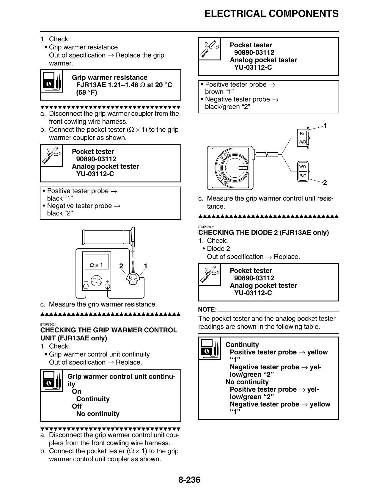
b. Connect the pocket tester (Ω × 1) to the grip                                                  Br
   warmer coupler as shown.
                                                                                                  W/B

             Pocket tester                                           HI

              90890-03112
             Analog pocket tester                                                                 W/Y
              YU-03112-C                                        LO                                B/G
                                                                     OFF
 • Positive tester probe →
   black “1”                                        c. Measure the grip warmer control unit resis-
 • Negative tester probe →                             tance.
   black “2”                                        ▲▲▲▲▲▲▲▲▲▲▲▲▲▲▲▲▲▲▲▲▲▲▲▲▲▲▲▲▲▲▲▲

                                                    ET3P66025

                                                    CHECKING THE DIODE 2 (FJR13AE only)
                                                    1. Check:
                                                     • Diode 2
                                                       Out of specification → Replace.

                                                                           Pocket tester
                                                                            90890-03112
                                                                           Analog pocket tester
                                                                            YU-03112-C
c. Measure the grip warmer resistance.
                                                    NOTE:
▲▲▲▲▲▲▲▲▲▲▲▲▲▲▲▲▲▲▲▲▲▲▲▲▲▲▲▲▲▲▲▲
                                                    The pocket tester and the analog pocket tester
ET3P66024
                                                    readings are shown in the following table.
CHECKING THE GRIP WARMER CONTROL
UNIT (FJR13AE only)
1. Check:                                                             Continuity
 • Grip warmer control unit continuity                                 Positive tester probe → yellow
   Out of specification → Replace.                                     “1”
                                                                       Negative tester probe → yel-
            Grip warmer control unit continu-                          low/green “2”
            ity                                                       No continuity
              On                                                       Positive tester probe → yel-
                Continuity                                             low/green “2”
              Off                                                      Negative tester probe → yellow
                No continuity                                          “1”

▼▼▼▼▼▼▼▼▼▼▼▼▼▼▼▼▼▼▼▼▼▼▼▼▼▼▼▼▼▼▼▼
a. Disconnect the grip warmer control unit cou-
   plers from the front cowling wire harness.
b. Connect the pocket tester (Ω × 1) to the grip
   warmer control unit coupler as shown.

                                                8-236
                                                        ELECTRICAL COMPONENTS

                             Y

                           Y/G

▼▼▼▼▼▼▼▼▼▼▼▼▼▼▼▼▼▼▼▼▼▼▼▼▼▼▼▼▼▼▼▼
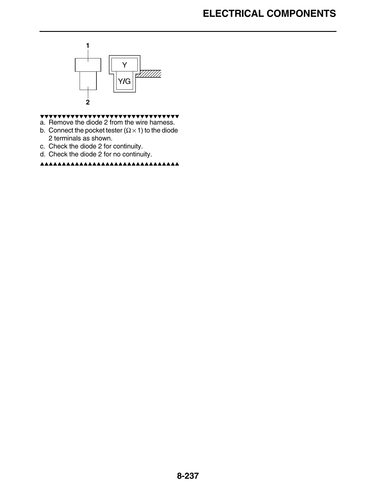
a. Remove the diode 2 from the wire harness.
b. Connect the pocket tester (Ω × 1) to the diode
   2 terminals as shown.
c. Check the diode 2 for continuity.
d. Check the diode 2 for no continuity.
▲▲▲▲▲▲▲▲▲▲▲▲▲▲▲▲▲▲▲▲▲▲▲▲▲▲▲▲▲▲▲▲

                                                8-237