Checking The Gear Position Sensor (FJR13AE Only)
Fragment manuala — str. 706
📋 Tekst do skopiowania / wyszukiwania
ELECTRICAL COMPONENTS
ET3P66021
3. Install:
CHECKING THE GEAR POSITION SENSOR
• Gear position sensor
(FJR13AE only)
Refer to “INSTALLING THE GEAR POSI-
1. Remove:
TION SENSOR (FJR13AE only)” on page
• Gear position sensor
5-11.
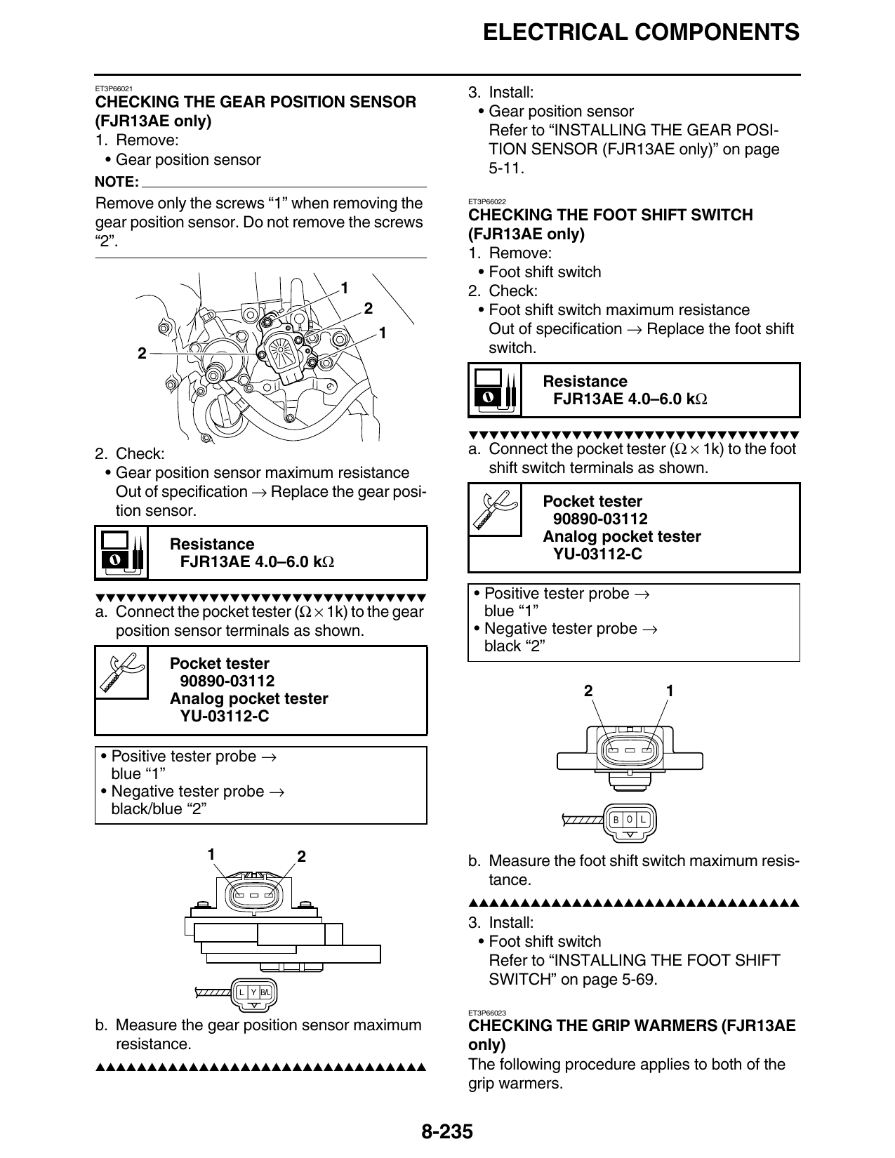
NOTE:
Remove only the screws “1” when removing the ET3P66022
gear position sensor. Do not remove the screws CHECKING THE FOOT SHIFT SWITCH
“2”. (FJR13AE only)
1. Remove:
• Foot shift switch
1 2. Check:
2 • Foot shift switch maximum resistance
1 Out of specification → Replace the foot shift
2 switch.
Resistance
FJR13AE 4.0–6.0 kΩ
▼▼▼▼▼▼▼▼▼▼▼▼▼▼▼▼▼▼▼▼▼▼▼▼▼▼▼▼▼▼▼▼
2. Check: a. Connect the pocket tester (Ω × 1k) to the foot
• Gear position sensor maximum resistance shift switch terminals as shown.
Out of specification → Replace the gear posi-
Pocket tester
tion sensor. 90890-03112
Resistance Analog pocket tester
FJR13AE 4.0–6.0 kΩ YU-03112-C
▼▼▼▼▼▼▼▼▼▼▼▼▼▼▼▼▼▼▼▼▼▼▼▼▼▼▼▼▼▼▼▼ • Positive tester probe →
a. Connect the pocket tester (Ω × 1k) to the gear blue “1”
position sensor terminals as shown. • Negative tester probe →
black “2”
Pocket tester
90890-03112
Analog pocket tester 2 1
YU-03112-C
• Positive tester probe →
blue “1”
• Negative tester probe →
black/blue “2”
B O L
1 2 b. Measure the foot shift switch maximum resis-
tance.
▲▲▲▲▲▲▲▲▲▲▲▲▲▲▲▲▲▲▲▲▲▲▲▲▲▲▲▲▲▲▲▲
3. Install:
• Foot shift switch
Refer to “INSTALLING THE FOOT SHIFT
SWITCH” on page 5-69.
L Y B/L
ET3P66023
b. Measure the gear position sensor maximum CHECKING THE GRIP WARMERS (FJR13AE
resistance. only)
▲▲▲▲▲▲▲▲▲▲▲▲▲▲▲▲▲▲▲▲▲▲▲▲▲▲▲▲▲▲▲▲ The following procedure applies to both of the
grip warmers.
8-235