Self-diagnostic Function Table
Fragment manuala — str. 537–538
📋 Tekst do skopiowania / wyszukiwania
FUEL INJECTION SYSTEM
a b
c d c
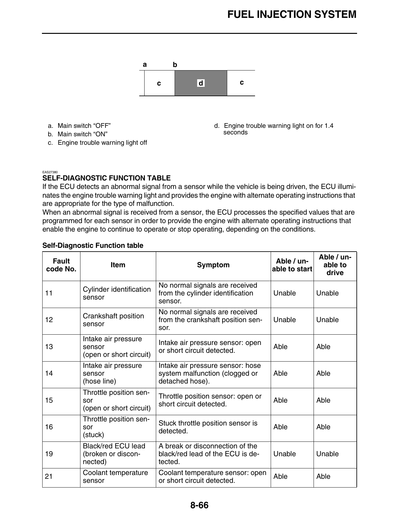
a. Main switch “OFF” d. Engine trouble warning light on for 1.4
b. Main switch “ON” seconds
c. Engine trouble warning light off
EAS27380
SELF-DIAGNOSTIC FUNCTION TABLE
If the ECU detects an abnormal signal from a sensor while the vehicle is being driven, the ECU illumi-
nates the engine trouble warning light and provides the engine with alternate operating instructions that
are appropriate for the type of malfunction.
When an abnormal signal is received from a sensor, the ECU processes the specified values that are
programmed for each sensor in order to provide the engine with alternate operating instructions that
enable the engine to continue to operate or stop operating, depending on the conditions.
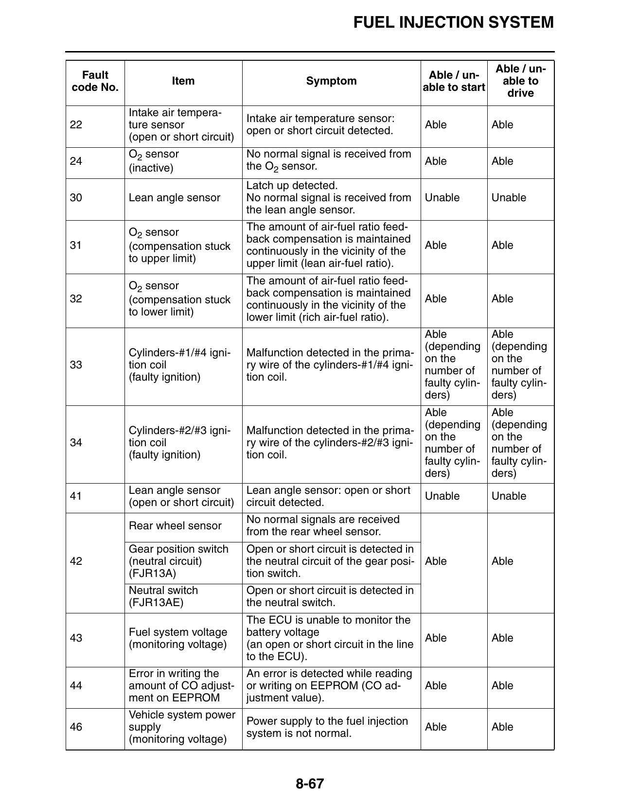
Self-Diagnostic Function table
Able / un-
Fault Able / un-
Item Symptom able to
code No. able to start
drive
No normal signals are received
Cylinder identification
11 from the cylinder identification Unable Unable
sensor
sensor.
No normal signals are received
Crankshaft position
12 from the crankshaft position sen- Unable Unable
sensor
sor.
Intake air pressure
Intake air pressure sensor: open
13 sensor Able Able
or short circuit detected.
(open or short circuit)
Intake air pressure Intake air pressure sensor: hose
14 sensor system malfunction (clogged or Able Able
(hose line) detached hose).
Throttle position sen-
Throttle position sensor: open or
15 sor Able Able
short circuit detected.
(open or short circuit)
Throttle position sen-
Stuck throttle position sensor is
16 sor Able Able
detected.
(stuck)
Black/red ECU lead A break or disconnection of the
19 (broken or discon- black/red lead of the ECU is de- Unable Unable
nected) tected.
Coolant temperature Coolant temperature sensor: open
21 Able Able
sensor or short circuit detected.
8-66
FUEL INJECTION SYSTEM
Able / un-
Fault Able / un-
Item Symptom able to
code No. able to start
drive
Intake air tempera-
Intake air temperature sensor:
22 ture sensor Able Able
open or short circuit detected.
(open or short circuit)
O2 sensor No normal signal is received from
24 the O2 sensor. Able Able
(inactive)
Latch up detected.
30 Lean angle sensor No normal signal is received from Unable Unable
the lean angle sensor.
O2 sensor The amount of air-fuel ratio feed-
back compensation is maintained
31 (compensation stuck Able Able
continuously in the vicinity of the
to upper limit) upper limit (lean air-fuel ratio).
O2 sensor The amount of air-fuel ratio feed-
back compensation is maintained
32 (compensation stuck Able Able
continuously in the vicinity of the
to lower limit) lower limit (rich air-fuel ratio).
Able Able
(depending (depending
Cylinders-#1/#4 igni- Malfunction detected in the prima-
on the on the
33 tion coil ry wire of the cylinders-#1/#4 igni-
number of number of
(faulty ignition) tion coil.
faulty cylin- faulty cylin-
ders) ders)
Able Able
(depending (depending
Cylinders-#2/#3 igni- Malfunction detected in the prima-
on the on the
34 tion coil ry wire of the cylinders-#2/#3 igni-
number of number of
(faulty ignition) tion coil.
faulty cylin- faulty cylin-
ders) ders)
Lean angle sensor Lean angle sensor: open or short
41 Unable Unable
(open or short circuit) circuit detected.
No normal signals are received
Rear wheel sensor
from the rear wheel sensor.
Gear position switch Open or short circuit is detected in
42 (neutral circuit) the neutral circuit of the gear posi- Able Able
(FJR13A) tion switch.
Neutral switch Open or short circuit is detected in
(FJR13AE) the neutral switch.
The ECU is unable to monitor the
Fuel system voltage battery voltage
43 Able Able
(monitoring voltage) (an open or short circuit in the line
to the ECU).
Error in writing the An error is detected while reading
44 amount of CO adjust- or writing on EEPROM (CO ad- Able Able
ment on EEPROM justment value).
Vehicle system power
Power supply to the fuel injection
46 supply Able Able
system is not normal.
(monitoring voltage)
8-67