Self-diagnostic Function Table
Fragment manuala — str. 642–644
📋 Tekst do skopiowania / wyszukiwania
YCC-S (Yamaha Chip Controlled-Shift) SYSTEM (FJR13AE only)
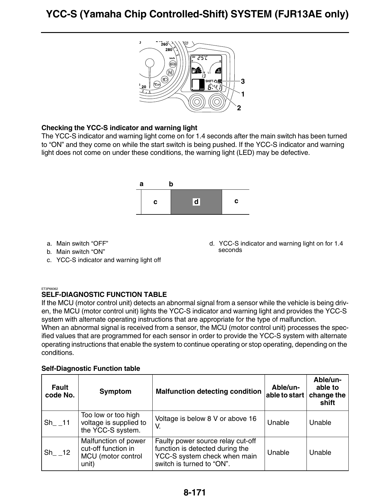
SHIFT 3
Checking the YCC-S indicator and warning light
The YCC-S indicator and warning light come on for 1.4 seconds after the main switch has been turned
to “ON” and they come on while the start switch is being pushed. If the YCC-S indicator and warning
light does not come on under these conditions, the warning light (LED) may be defective.
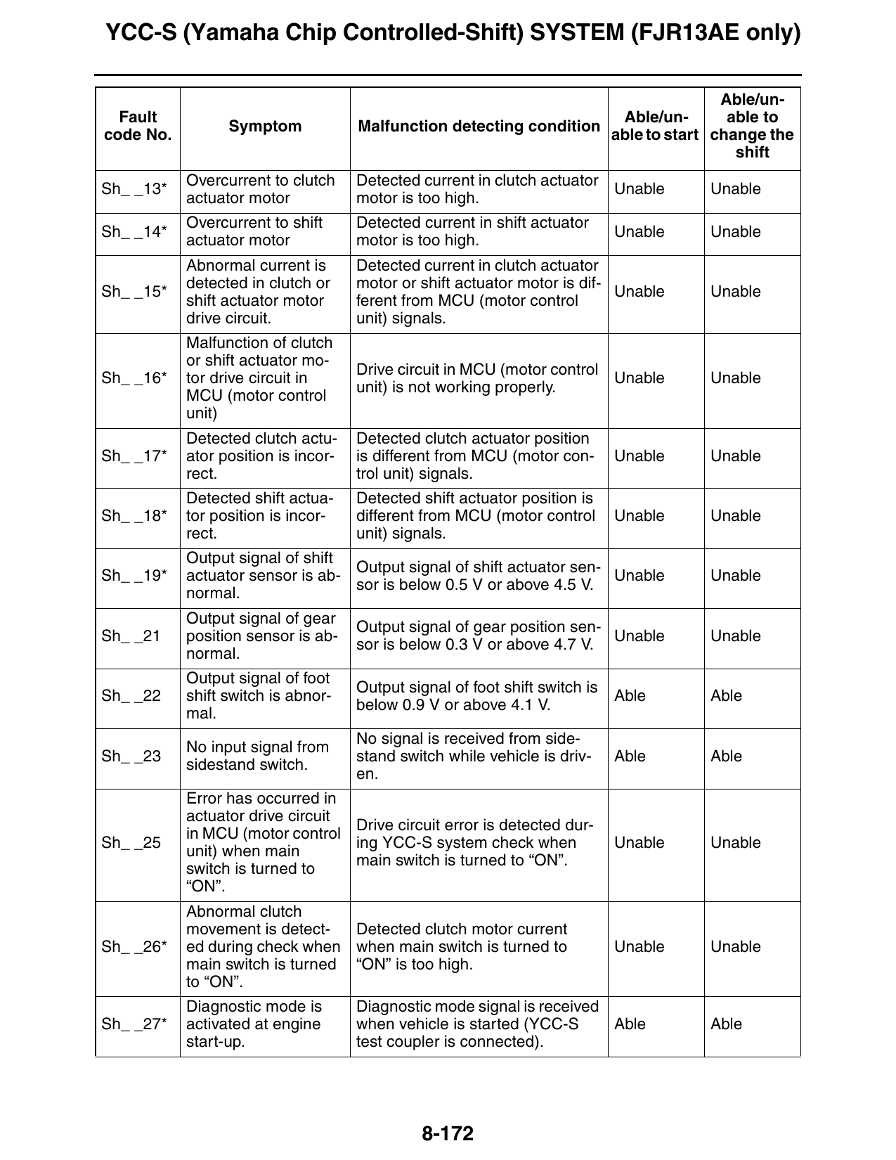
a b
c d c
a. Main switch “OFF” d. YCC-S indicator and warning light on for 1.4
b. Main switch “ON” seconds
c. YCC-S indicator and warning light off
ET3P66062
SELF-DIAGNOSTIC FUNCTION TABLE
If the MCU (motor control unit) detects an abnormal signal from a sensor while the vehicle is being driv-
en, the MCU (motor control unit) lights the YCC-S indicator and warning light and provides the YCC-S
system with alternate operating instructions that are appropriate for the type of malfunction.
When an abnormal signal is received from a sensor, the MCU (motor control unit) processes the spec-
ified values that are programmed for each sensor in order to provide the YCC-S system with alternate
operating instructions that enable the system to continue operating or stop operating, depending on the
conditions.
Self-Diagnostic Function table
Able/un-
Fault Able/un- able to
Symptom Malfunction detecting condition
code No. able to start change the
shift
Too low or too high
Voltage is below 8 V or above 16
Sh_ _11 voltage is supplied to Unable Unable
V.
the YCC-S system.
Malfunction of power Faulty power source relay cut-off
cut-off function in function is detected during the
Sh_ _12 Unable Unable
MCU (motor control YCC-S system check when main
unit) switch is turned to “ON”.
8-171
YCC-S (Yamaha Chip Controlled-Shift) SYSTEM (FJR13AE only)
Able/un-
Fault Able/un- able to
Symptom Malfunction detecting condition
code No. able to start change the
shift
Overcurrent to clutch Detected current in clutch actuator
Sh_ _13* Unable Unable
actuator motor motor is too high.
Overcurrent to shift Detected current in shift actuator
Sh_ _14* Unable Unable
actuator motor motor is too high.
Abnormal current is Detected current in clutch actuator
detected in clutch or motor or shift actuator motor is dif-
Sh_ _15* Unable Unable
shift actuator motor ferent from MCU (motor control
drive circuit. unit) signals.
Malfunction of clutch
or shift actuator mo-
Drive circuit in MCU (motor control
Sh_ _16* tor drive circuit in Unable Unable
unit) is not working properly.
MCU (motor control
unit)
Detected clutch actu- Detected clutch actuator position
Sh_ _17* ator position is incor- is different from MCU (motor con- Unable Unable
rect. trol unit) signals.
Detected shift actua- Detected shift actuator position is
Sh_ _18* tor position is incor- different from MCU (motor control Unable Unable
rect. unit) signals.
Output signal of shift
Output signal of shift actuator sen-
Sh_ _19* actuator sensor is ab- Unable Unable
sor is below 0.5 V or above 4.5 V.
normal.
Output signal of gear
Output signal of gear position sen-
Sh_ _21 position sensor is ab- Unable Unable
sor is below 0.3 V or above 4.7 V.
normal.
Output signal of foot
Output signal of foot shift switch is
Sh_ _22 shift switch is abnor- Able Able
below 0.9 V or above 4.1 V.
mal.
No signal is received from side-
No input signal from
Sh_ _23 stand switch while vehicle is driv- Able Able
sidestand switch.
en.
Error has occurred in
actuator drive circuit
Drive circuit error is detected dur-
in MCU (motor control
Sh_ _25 ing YCC-S system check when Unable Unable
unit) when main
main switch is turned to “ON”.
switch is turned to
“ON”.
Abnormal clutch
movement is detect- Detected clutch motor current
Sh_ _26* ed during check when when main switch is turned to Unable Unable
main switch is turned “ON” is too high.
to “ON”.
Diagnostic mode is Diagnostic mode signal is received
Sh_ _27* activated at engine when vehicle is started (YCC-S Able Able
start-up. test coupler is connected).
8-172
YCC-S (Yamaha Chip Controlled-Shift) SYSTEM (FJR13AE only)
Able/un-
Fault Able/un- able to
Symptom Malfunction detecting condition
code No. able to start change the
shift
Engine speed signal from ECU
Engine speed signal
Sh_ _31 does not match multi-function Unable Unable
is abnormal.
meter engine speed.
YCC-S speed sensor signal does
YCC-S speed sensor
Sh_ _32* not match multi-function meter ve- Unable Unable
signal is abnormal.
hicle speed.
TPS (throttle position
TPS (throttle position sensor) sig-
Sh_ _34 sensor) signal is ab- Unable Able
nal voltage is too low or too high
normal.
Start switch signal is Signal is received from start switch
Sh_ _35 Able Able
abnormal. while vehicle is driven.
Signals received from clutch actu-
Output signal of clutch
ator sensor 1 and clutch actuator
Sh_ _36 actuator sensor is ab- Unable Unable
sensor 2 are different or signal
normal.
voltage is too low or too high.
Power supply to
Battery voltage is good, but motor
Sh_ _37* clutch or shift actuator Unable Unable
terminal voltage is too low.
motor is abnormal.
Both the on and off circuits of the
Malfunction of hand
hand shift lever switch (shift up or
Sh_ _38 shift lever switch (shift Able Able
shift down) are closed at the same
up or shift down)
time.
Ignition timing retard Detected ignition retard signal
Sh_ _39 output signal is abnor- from MCU (motor control unit) to Able Able
mal. ECU is abnormal.
Coolant temperature
Coolant temperature sensor signal
Sh_ _41 sensor signal is ab- Able Able
is too high or too low
normal.
Communication be-
Error detected in communication
tween ECU and multi-
Sh_ _42 signal between ECU and multi- Unable Able
function meter is ab-
function meter.
normal.
Communication be-
tween MCU (motor ABS ECU continuously sends sig-
Sh_ _43 Able Able
control unit) and ABS nals to activate ABS.
ECU is abnormal.
Clutch is completely engaged, but
Clutch actuator sen-
signal sent from clutch actuator
Sh_ _44* sor signal is abnor- Unable Unable
sensor indicates clutch is disen-
mal.
gaged.
Shift operation and Gear position has not changed af-
Sh_ _45* gear position do not ter shifting by shift actuator (mis- Unable Unable
match. shift occurs repeatedly).
Engine speed and
Gear position calculated by MCU
gear position sensor
Sh_ _46* (motor control unit) is different Unable Unable
signal do not match
from foot shift switch signal.
while vehicle is driven.
8-173