Troubleshooting
Fragment manuala — str. 518–523
📋 Tekst do skopiowania / wyszukiwania
SIGNALING SYSTEM
EAS27290
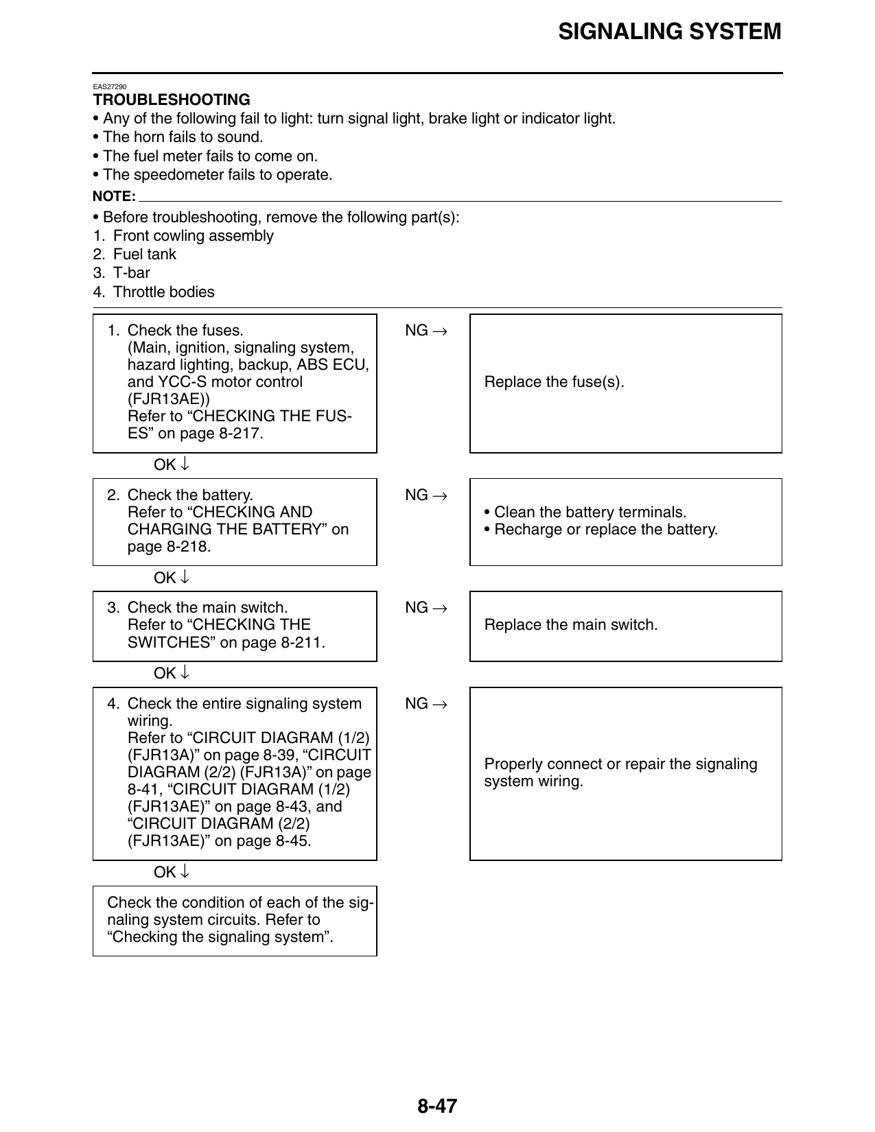
TROUBLESHOOTING
• Any of the following fail to light: turn signal light, brake light or indicator light.
• The horn fails to sound.
• The fuel meter fails to come on.
• The speedometer fails to operate.
NOTE:
• Before troubleshooting, remove the following part(s):
1. Front cowling assembly
2. Fuel tank
3. T-bar
4. Throttle bodies
1. Check the fuses. NG →
(Main, ignition, signaling system,
hazard lighting, backup, ABS ECU,
and YCC-S motor control Replace the fuse(s).
(FJR13AE))
Refer to “CHECKING THE FUS-
ES” on page 8-217.
OK ↓
2. Check the battery. NG →
Refer to “CHECKING AND • Clean the battery terminals.
CHARGING THE BATTERY” on • Recharge or replace the battery.
page 8-218.
OK ↓
3. Check the main switch. NG →
Refer to “CHECKING THE Replace the main switch.
SWITCHES” on page 8-211.
OK ↓
4. Check the entire signaling system NG →
wiring.
Refer to “CIRCUIT DIAGRAM (1/2)
(FJR13A)” on page 8-39, “CIRCUIT
Properly connect or repair the signaling
DIAGRAM (2/2) (FJR13A)” on page
system wiring.
8-41, “CIRCUIT DIAGRAM (1/2)
(FJR13AE)” on page 8-43, and
“CIRCUIT DIAGRAM (2/2)
(FJR13AE)” on page 8-45.
OK ↓
Check the condition of each of the sig-
naling system circuits. Refer to
“Checking the signaling system”.
8-47
SIGNALING SYSTEM
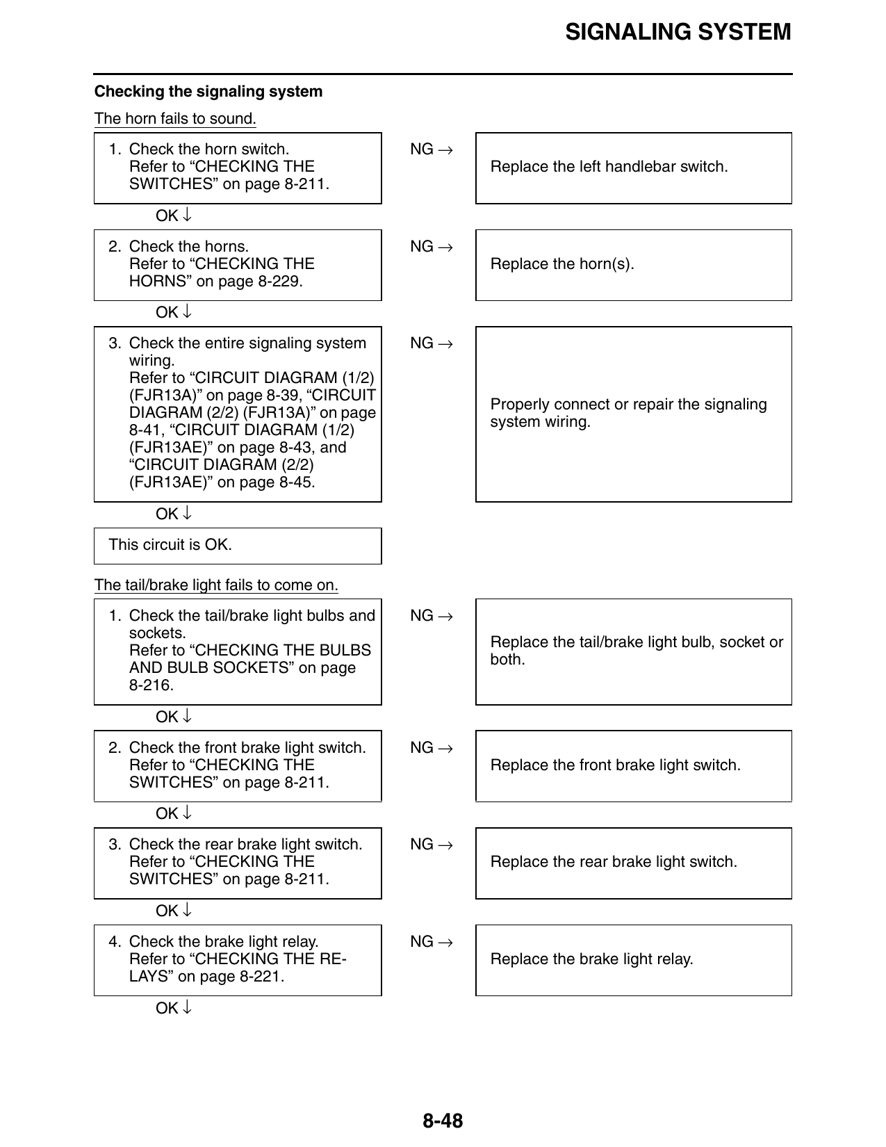
Checking the signaling system
The horn fails to sound.
1. Check the horn switch. NG →
Refer to “CHECKING THE Replace the left handlebar switch.
SWITCHES” on page 8-211.
OK ↓
2. Check the horns. NG →
Refer to “CHECKING THE Replace the horn(s).
HORNS” on page 8-229.
OK ↓
3. Check the entire signaling system NG →
wiring.
Refer to “CIRCUIT DIAGRAM (1/2)
(FJR13A)” on page 8-39, “CIRCUIT
Properly connect or repair the signaling
DIAGRAM (2/2) (FJR13A)” on page
system wiring.
8-41, “CIRCUIT DIAGRAM (1/2)
(FJR13AE)” on page 8-43, and
“CIRCUIT DIAGRAM (2/2)
(FJR13AE)” on page 8-45.
OK ↓
This circuit is OK.
The tail/brake light fails to come on.
1. Check the tail/brake light bulbs and NG →
sockets.
Replace the tail/brake light bulb, socket or
Refer to “CHECKING THE BULBS
both.
AND BULB SOCKETS” on page
8-216.
OK ↓
2. Check the front brake light switch. NG →
Refer to “CHECKING THE Replace the front brake light switch.
SWITCHES” on page 8-211.
OK ↓
3. Check the rear brake light switch. NG →
Refer to “CHECKING THE Replace the rear brake light switch.
SWITCHES” on page 8-211.
OK ↓
4. Check the brake light relay. NG →
Refer to “CHECKING THE RE- Replace the brake light relay.
LAYS” on page 8-221.
OK ↓
8-48
SIGNALING SYSTEM
NG →
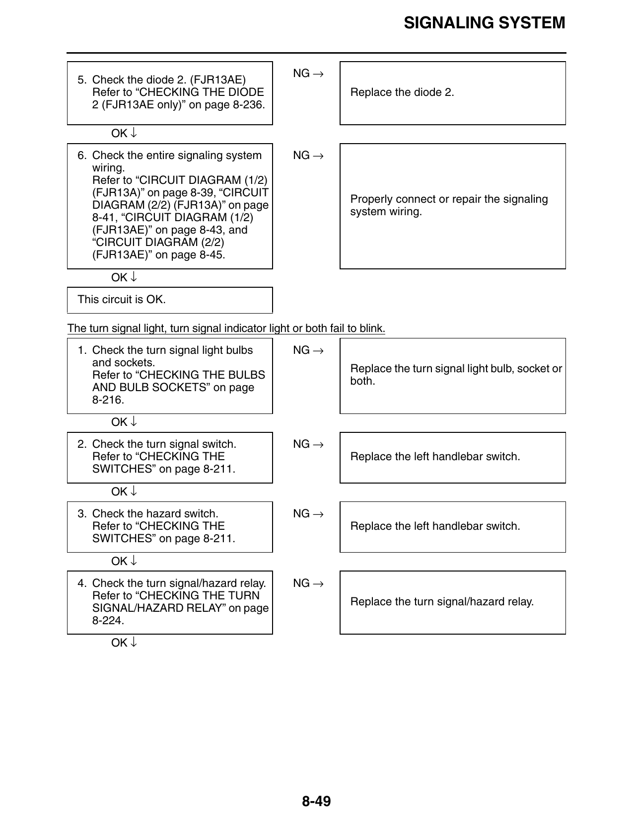
5. Check the diode 2. (FJR13AE)
Refer to “CHECKING THE DIODE Replace the diode 2.
2 (FJR13AE only)” on page 8-236.
OK ↓
6. Check the entire signaling system NG →
wiring.
Refer to “CIRCUIT DIAGRAM (1/2)
(FJR13A)” on page 8-39, “CIRCUIT
Properly connect or repair the signaling
DIAGRAM (2/2) (FJR13A)” on page
system wiring.
8-41, “CIRCUIT DIAGRAM (1/2)
(FJR13AE)” on page 8-43, and
“CIRCUIT DIAGRAM (2/2)
(FJR13AE)” on page 8-45.
OK ↓
This circuit is OK.
The turn signal light, turn signal indicator light or both fail to blink.
1. Check the turn signal light bulbs NG →
and sockets.
Replace the turn signal light bulb, socket or
Refer to “CHECKING THE BULBS
both.
AND BULB SOCKETS” on page
8-216.
OK ↓
2. Check the turn signal switch. NG →
Refer to “CHECKING THE Replace the left handlebar switch.
SWITCHES” on page 8-211.
OK ↓
3. Check the hazard switch. NG →
Refer to “CHECKING THE Replace the left handlebar switch.
SWITCHES” on page 8-211.
OK ↓
4. Check the turn signal/hazard relay. NG →
Refer to “CHECKING THE TURN
Replace the turn signal/hazard relay.
SIGNAL/HAZARD RELAY” on page
8-224.
OK ↓
8-49
SIGNALING SYSTEM
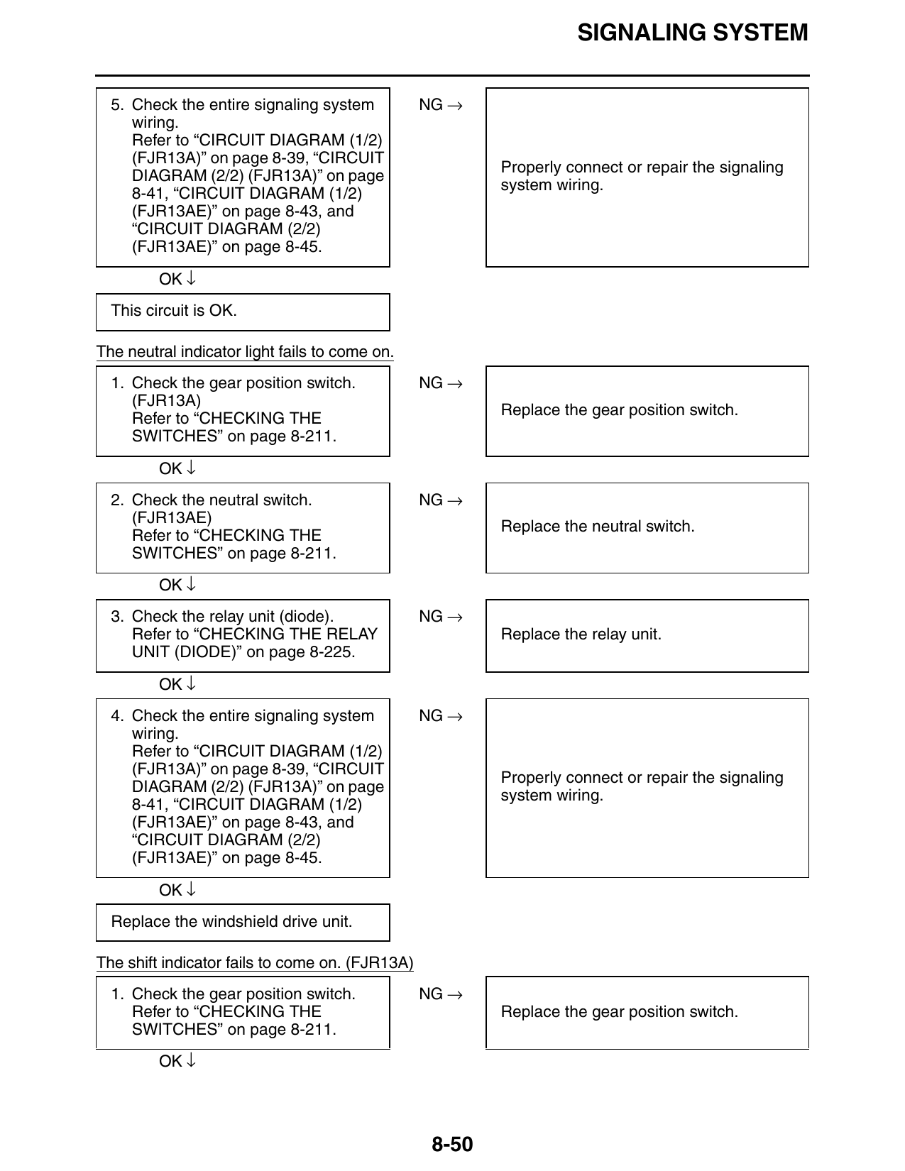
5. Check the entire signaling system NG →
wiring.
Refer to “CIRCUIT DIAGRAM (1/2)
(FJR13A)” on page 8-39, “CIRCUIT
Properly connect or repair the signaling
DIAGRAM (2/2) (FJR13A)” on page
system wiring.
8-41, “CIRCUIT DIAGRAM (1/2)
(FJR13AE)” on page 8-43, and
“CIRCUIT DIAGRAM (2/2)
(FJR13AE)” on page 8-45.
OK ↓
This circuit is OK.
The neutral indicator light fails to come on.
1. Check the gear position switch. NG →
(FJR13A)
Replace the gear position switch.
Refer to “CHECKING THE
SWITCHES” on page 8-211.
OK ↓
2. Check the neutral switch. NG →
(FJR13AE)
Replace the neutral switch.
Refer to “CHECKING THE
SWITCHES” on page 8-211.
OK ↓
3. Check the relay unit (diode). NG →
Refer to “CHECKING THE RELAY Replace the relay unit.
UNIT (DIODE)” on page 8-225.
OK ↓
4. Check the entire signaling system NG →
wiring.
Refer to “CIRCUIT DIAGRAM (1/2)
(FJR13A)” on page 8-39, “CIRCUIT
Properly connect or repair the signaling
DIAGRAM (2/2) (FJR13A)” on page
system wiring.
8-41, “CIRCUIT DIAGRAM (1/2)
(FJR13AE)” on page 8-43, and
“CIRCUIT DIAGRAM (2/2)
(FJR13AE)” on page 8-45.
OK ↓
Replace the windshield drive unit.
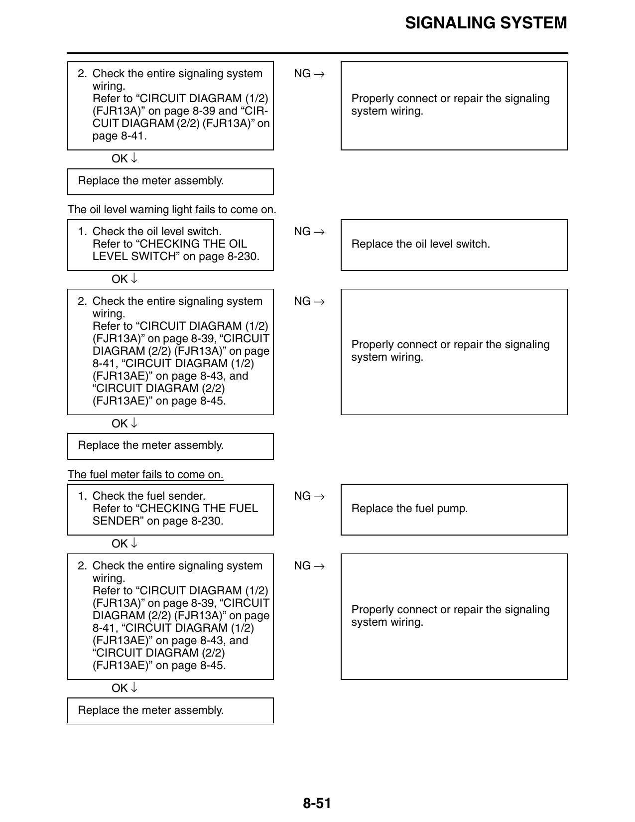
The shift indicator fails to come on. (FJR13A)
1. Check the gear position switch. NG →
Refer to “CHECKING THE Replace the gear position switch.
SWITCHES” on page 8-211.
OK ↓
8-50
SIGNALING SYSTEM
2. Check the entire signaling system NG →
wiring.
Refer to “CIRCUIT DIAGRAM (1/2) Properly connect or repair the signaling
(FJR13A)” on page 8-39 and “CIR- system wiring.
CUIT DIAGRAM (2/2) (FJR13A)” on
page 8-41.
OK ↓
Replace the meter assembly.
The oil level warning light fails to come on.
1. Check the oil level switch. NG →
Refer to “CHECKING THE OIL Replace the oil level switch.
LEVEL SWITCH” on page 8-230.
OK ↓
2. Check the entire signaling system NG →
wiring.
Refer to “CIRCUIT DIAGRAM (1/2)
(FJR13A)” on page 8-39, “CIRCUIT
Properly connect or repair the signaling
DIAGRAM (2/2) (FJR13A)” on page
system wiring.
8-41, “CIRCUIT DIAGRAM (1/2)
(FJR13AE)” on page 8-43, and
“CIRCUIT DIAGRAM (2/2)
(FJR13AE)” on page 8-45.
OK ↓
Replace the meter assembly.
The fuel meter fails to come on.
1. Check the fuel sender. NG →
Refer to “CHECKING THE FUEL Replace the fuel pump.
SENDER” on page 8-230.
OK ↓
2. Check the entire signaling system NG →
wiring.
Refer to “CIRCUIT DIAGRAM (1/2)
(FJR13A)” on page 8-39, “CIRCUIT
Properly connect or repair the signaling
DIAGRAM (2/2) (FJR13A)” on page
system wiring.
8-41, “CIRCUIT DIAGRAM (1/2)
(FJR13AE)” on page 8-43, and
“CIRCUIT DIAGRAM (2/2)
(FJR13AE)” on page 8-45.
OK ↓
Replace the meter assembly.
8-51
SIGNALING SYSTEM
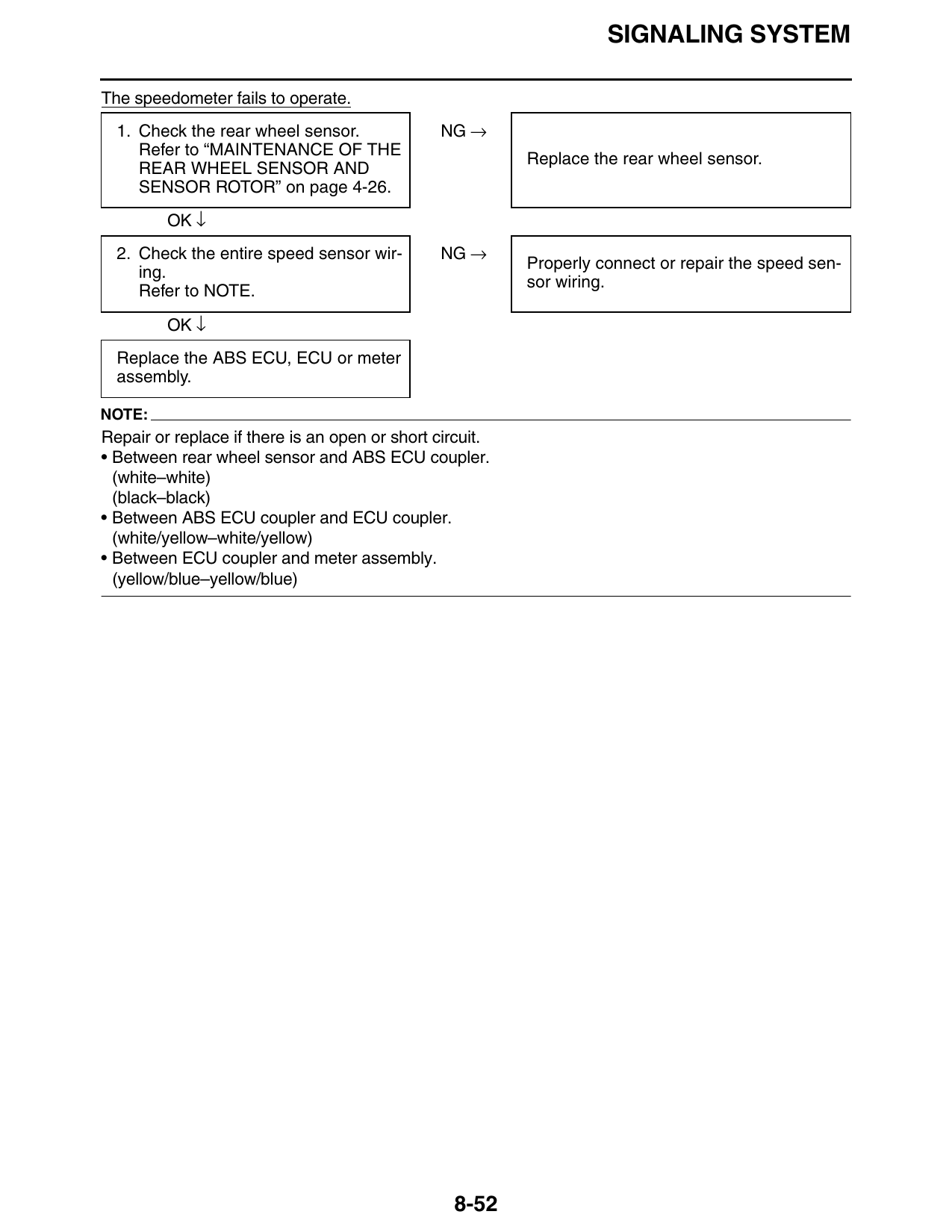
The speedometer fails to operate.
1. Check the rear wheel sensor. NG →
Refer to “MAINTENANCE OF THE
Replace the rear wheel sensor.
REAR WHEEL SENSOR AND
SENSOR ROTOR” on page 4-26.
OK ↓
2. Check the entire speed sensor wir- NG →
Properly connect or repair the speed sen-
ing.
sor wiring.
Refer to NOTE.
OK ↓
Replace the ABS ECU, ECU or meter
assembly.
NOTE:
Repair or replace if there is an open or short circuit.
• Between rear wheel sensor and ABS ECU coupler.
(white–white)
(black–black)
• Between ABS ECU coupler and ECU coupler.
(white/yellow–white/yellow)
• Between ECU coupler and meter assembly.
(yellow/blue–yellow/blue)
8-52