ABS Operation
Fragment manuala — str. 25–28
📋 Tekst do skopiowania / wyszukiwania
FEATURES
1 10
4 14
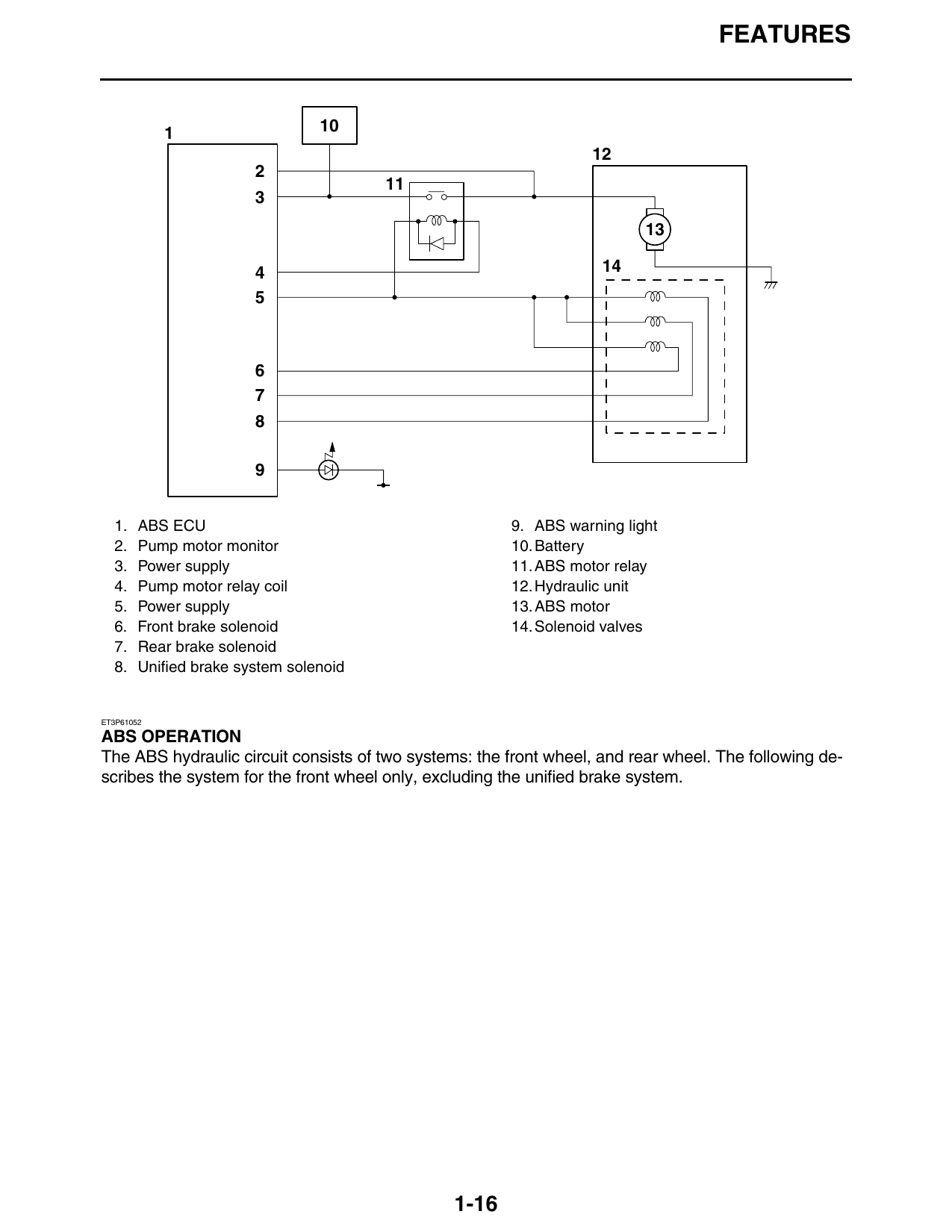
1. ABS ECU 9. ABS warning light
2. Pump motor monitor 10. Battery
3. Power supply 11. ABS motor relay
4. Pump motor relay coil 12. Hydraulic unit
5. Power supply 13. ABS motor
6. Front brake solenoid 14. Solenoid valves
7. Rear brake solenoid
8. Unified brake system solenoid
ET3P61052
ABS OPERATION
The ABS hydraulic circuit consists of two systems: the front wheel, and rear wheel. The following de-
scribes the system for the front wheel only, excluding the unified brake system.
1-16
FEATURES
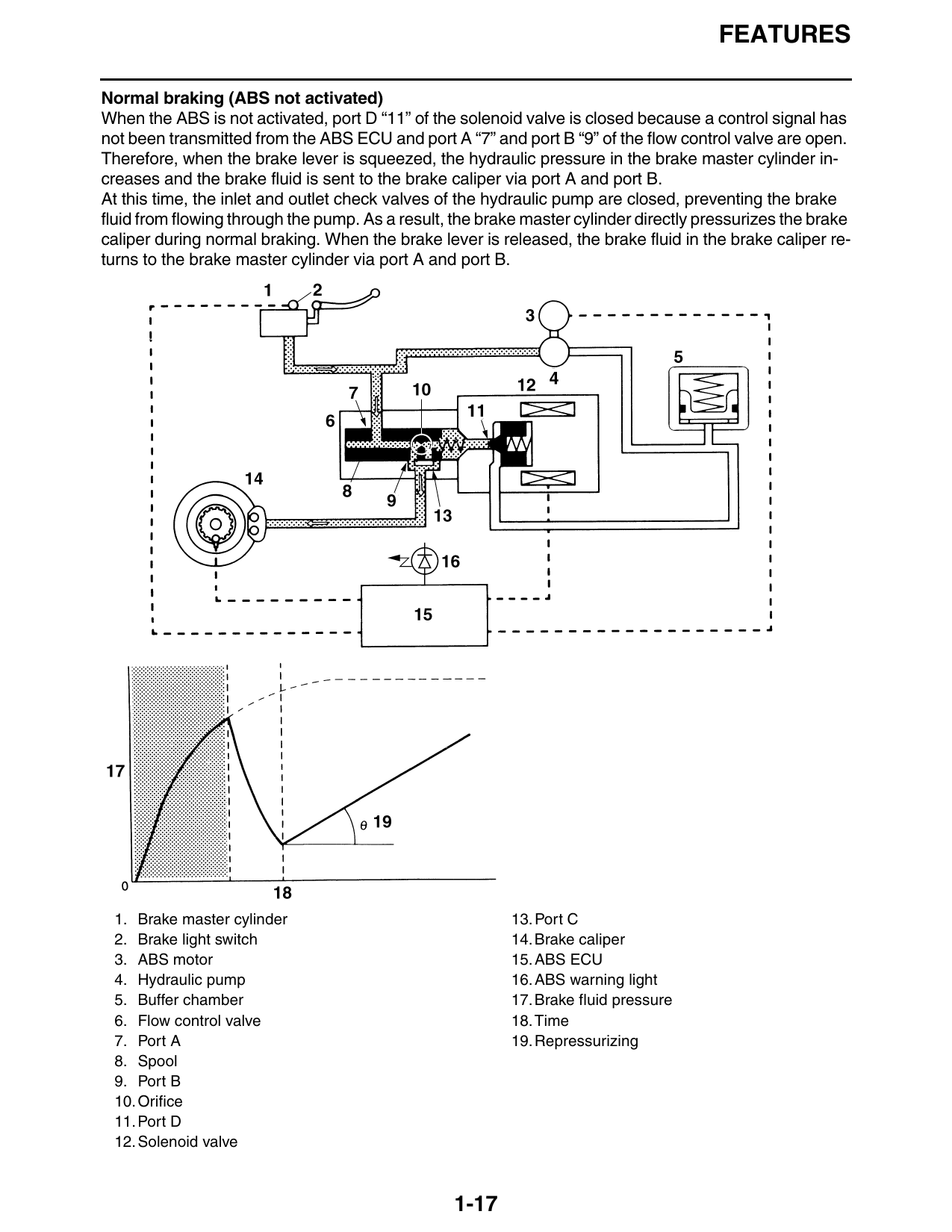
Normal braking (ABS not activated)
When the ABS is not activated, port D “11” of the solenoid valve is closed because a control signal has
not been transmitted from the ABS ECU and port A “7” and port B “9” of the flow control valve are open.
Therefore, when the brake lever is squeezed, the hydraulic pressure in the brake master cylinder in-
creases and the brake fluid is sent to the brake caliper via port A and port B.
At this time, the inlet and outlet check valves of the hydraulic pump are closed, preventing the brake
fluid from flowing through the pump. As a result, the brake master cylinder directly pressurizes the brake
caliper during normal braking. When the brake lever is released, the brake fluid in the brake caliper re-
turns to the brake master cylinder via port A and port B.
1. Brake master cylinder 13. Port C
2. Brake light switch 14. Brake caliper
3. ABS motor 15. ABS ECU
4. Hydraulic pump 16. ABS warning light
5. Buffer chamber 17. Brake fluid pressure
6. Flow control valve 18. Time
7. Port A 19. Repressurizing
8. Spool
9. Port B
10. Orifice
11. Port D
12. Solenoid valve
1-17
FEATURES
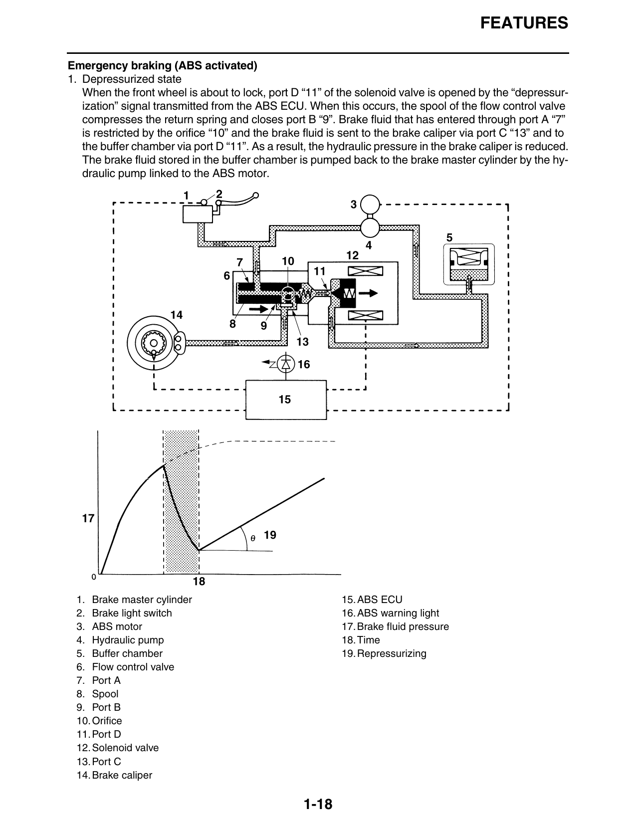
Emergency braking (ABS activated)
1. Depressurized state
When the front wheel is about to lock, port D “11” of the solenoid valve is opened by the “depressur-
ization” signal transmitted from the ABS ECU. When this occurs, the spool of the flow control valve
compresses the return spring and closes port B “9”. Brake fluid that has entered through port A “7”
is restricted by the orifice “10” and the brake fluid is sent to the brake caliper via port C “13” and to
the buffer chamber via port D “11”. As a result, the hydraulic pressure in the brake caliper is reduced.
The brake fluid stored in the buffer chamber is pumped back to the brake master cylinder by the hy-
draulic pump linked to the ABS motor.
1. Brake master cylinder 15. ABS ECU
2. Brake light switch 16. ABS warning light
3. ABS motor 17. Brake fluid pressure
4. Hydraulic pump 18. Time
5. Buffer chamber 19. Repressurizing
6. Flow control valve
7. Port A
8. Spool
9. Port B
10. Orifice
11. Port D
12. Solenoid valve
13. Port C
14. Brake caliper
1-18
FEATURES
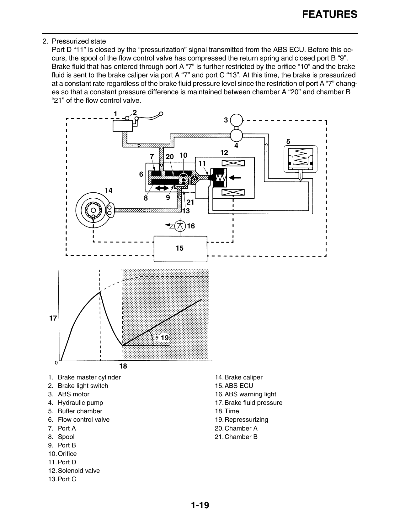
2. Pressurized state
Port D “11” is closed by the “pressurization” signal transmitted from the ABS ECU. Before this oc-
curs, the spool of the flow control valve has compressed the return spring and closed port B “9”.
Brake fluid that has entered through port A “7” is further restricted by the orifice “10” and the brake
fluid is sent to the brake caliper via port A “7” and port C “13”. At this time, the brake is pressurized
at a constant rate regardless of the brake fluid pressure level since the restriction of port A “7” chang-
es so that a constant pressure difference is maintained between chamber A “20” and chamber B
“21” of the flow control valve.
1. Brake master cylinder 14. Brake caliper
2. Brake light switch 15. ABS ECU
3. ABS motor 16. ABS warning light
4. Hydraulic pump 17. Brake fluid pressure
5. Buffer chamber 18. Time
6. Flow control valve 19. Repressurizing
7. Port A 20. Chamber A
8. Spool 21. Chamber B
9. Port B
10. Orifice
11. Port D
12. Solenoid valve
13. Port C
1-19