ABS Component Functions
Fragment manuala — str. 19–24
📋 Tekst do skopiowania / wyszukiwania
FEATURES
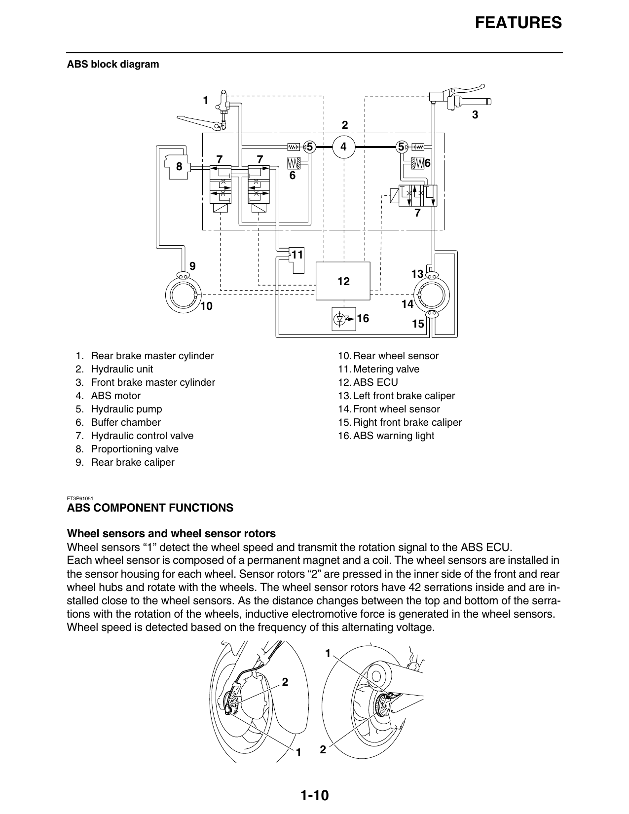
ABS block diagram
5 4 5
7 7 6
10 14
16 15
1. Rear brake master cylinder 10. Rear wheel sensor
2. Hydraulic unit 11. Metering valve
3. Front brake master cylinder 12. ABS ECU
4. ABS motor 13. Left front brake caliper
5. Hydraulic pump 14. Front wheel sensor
6. Buffer chamber 15. Right front brake caliper
7. Hydraulic control valve 16. ABS warning light
8. Proportioning valve
9. Rear brake caliper
ET3P61051
ABS COMPONENT FUNCTIONS
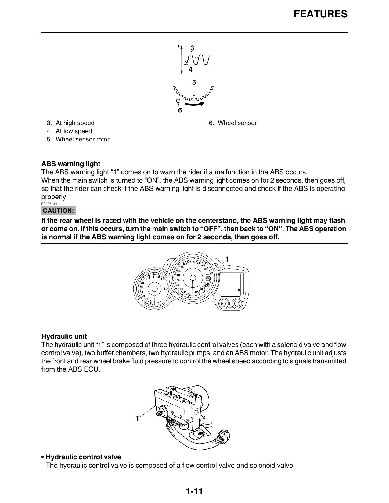
Wheel sensors and wheel sensor rotors
Wheel sensors “1” detect the wheel speed and transmit the rotation signal to the ABS ECU.
Each wheel sensor is composed of a permanent magnet and a coil. The wheel sensors are installed in
the sensor housing for each wheel. Sensor rotors “2” are pressed in the inner side of the front and rear
wheel hubs and rotate with the wheels. The wheel sensor rotors have 42 serrations inside and are in-
stalled close to the wheel sensors. As the distance changes between the top and bottom of the serra-
tions with the rotation of the wheels, inductive electromotive force is generated in the wheel sensors.
Wheel speed is detected based on the frequency of this alternating voltage.
1 2
1-10
FEATURES
3. At high speed 6. Wheel sensor
4. At low speed
5. Wheel sensor rotor
ABS warning light
The ABS warning light “1” comes on to warn the rider if a malfunction in the ABS occurs.
When the main switch is turned to “ON”, the ABS warning light comes on for 2 seconds, then goes off,
so that the rider can check if the ABS warning light is disconnected and check if the ABS is operating
properly.
EC3P61009
CAUTION:
If the rear wheel is raced with the vehicle on the centerstand, the ABS warning light may flash
or come on. If this occurs, turn the main switch to “OFF”, then back to “ON”. The ABS operation
is normal if the ABS warning light comes on for 2 seconds, then goes off.
Hydraulic unit
The hydraulic unit “1” is composed of three hydraulic control valves (each with a solenoid valve and flow
control valve), two buffer chambers, two hydraulic pumps, and an ABS motor. The hydraulic unit adjusts
the front and rear wheel brake fluid pressure to control the wheel speed according to signals transmitted
from the ABS ECU.
• Hydraulic control valve
The hydraulic control valve is composed of a flow control valve and solenoid valve.
1-11
FEATURES
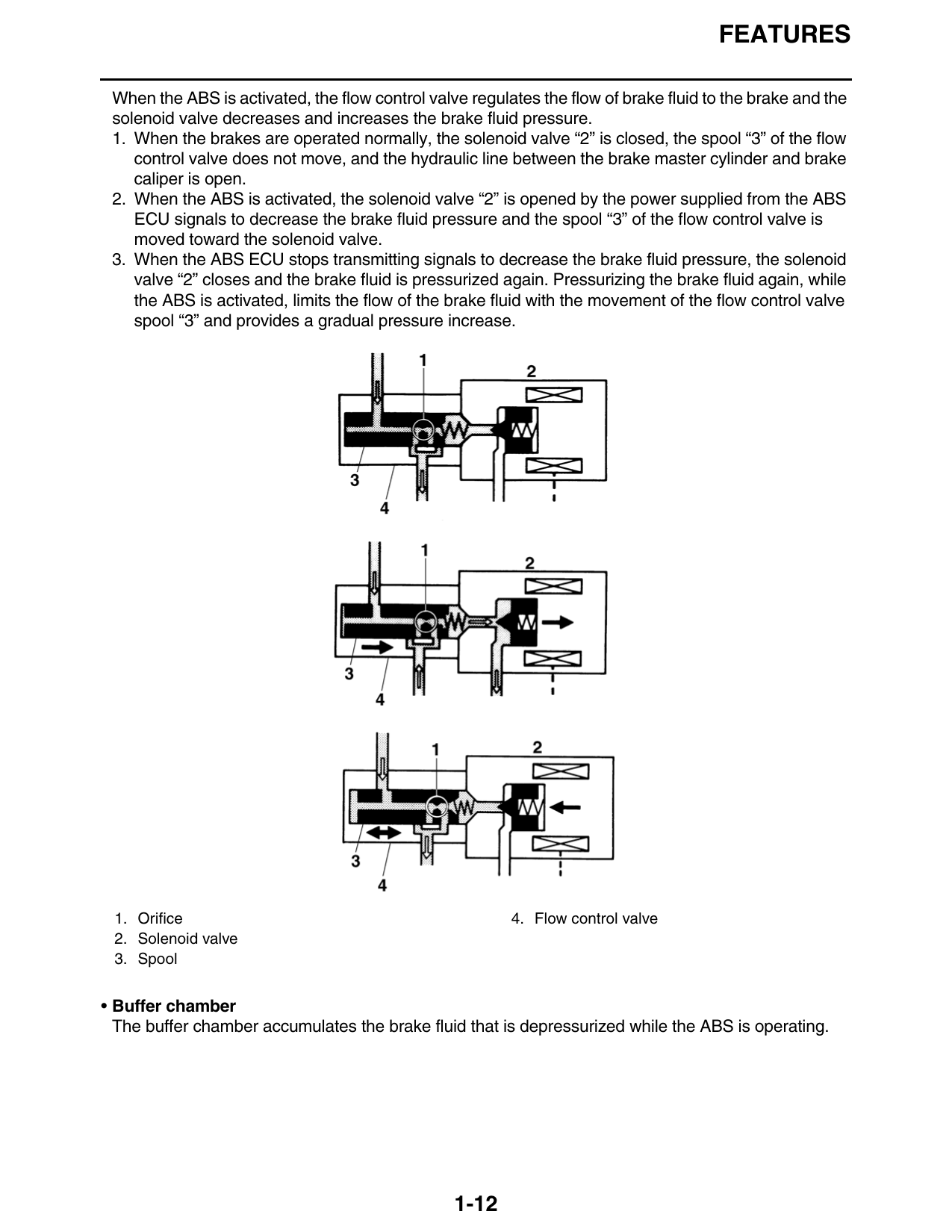
When the ABS is activated, the flow control valve regulates the flow of brake fluid to the brake and the
solenoid valve decreases and increases the brake fluid pressure.
1. When the brakes are operated normally, the solenoid valve “2” is closed, the spool “3” of the flow
control valve does not move, and the hydraulic line between the brake master cylinder and brake
caliper is open.
2. When the ABS is activated, the solenoid valve “2” is opened by the power supplied from the ABS
ECU signals to decrease the brake fluid pressure and the spool “3” of the flow control valve is
moved toward the solenoid valve.
3. When the ABS ECU stops transmitting signals to decrease the brake fluid pressure, the solenoid
valve “2” closes and the brake fluid is pressurized again. Pressurizing the brake fluid again, while
the ABS is activated, limits the flow of the brake fluid with the movement of the flow control valve
spool “3” and provides a gradual pressure increase.
1. Orifice 4. Flow control valve
2. Solenoid valve
3. Spool
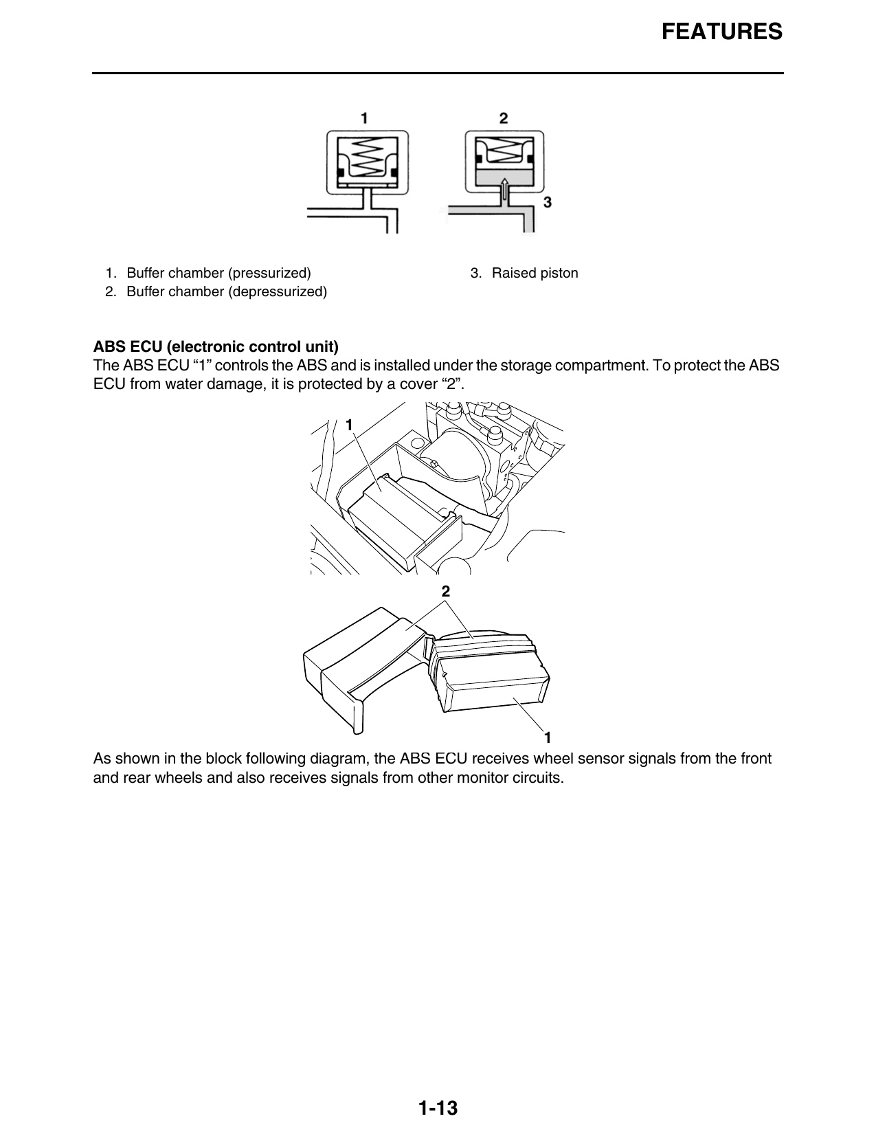
• Buffer chamber
The buffer chamber accumulates the brake fluid that is depressurized while the ABS is operating.
1-12
FEATURES
1. Buffer chamber (pressurized) 3. Raised piston
2. Buffer chamber (depressurized)
ABS ECU (electronic control unit)
The ABS ECU “1” controls the ABS and is installed under the storage compartment. To protect the ABS
ECU from water damage, it is protected by a cover “2”.
As shown in the block following diagram, the ABS ECU receives wheel sensor signals from the front
and rear wheels and also receives signals from other monitor circuits.
1-13
FEATURES
4 5 6
2 3 13
1 8
28 9
26 10 11 14
27 18 17 16
25 12
24 19
23 20
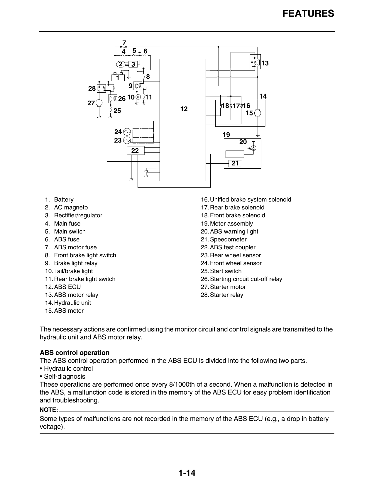
1. Battery 16. Unified brake system solenoid
2. AC magneto 17. Rear brake solenoid
3. Rectifier/regulator 18. Front brake solenoid
4. Main fuse 19. Meter assembly
5. Main switch 20. ABS warning light
6. ABS fuse 21. Speedometer
7. ABS motor fuse 22. ABS test coupler
8. Front brake light switch 23. Rear wheel sensor
9. Brake light relay 24. Front wheel sensor
10. Tail/brake light 25. Start switch
11. Rear brake light switch 26. Starting circuit cut-off relay
12. ABS ECU 27. Starter motor
13. ABS motor relay 28. Starter relay
14. Hydraulic unit
15. ABS motor
The necessary actions are confirmed using the monitor circuit and control signals are transmitted to the
hydraulic unit and ABS motor relay.
ABS control operation
The ABS control operation performed in the ABS ECU is divided into the following two parts.
• Hydraulic control
• Self-diagnosis
These operations are performed once every 8/1000th of a second. When a malfunction is detected in
the ABS, a malfunction code is stored in the memory of the ABS ECU for easy problem identification
and troubleshooting.
NOTE:
Some types of malfunctions are not recorded in the memory of the ABS ECU (e.g., a drop in battery
voltage).
1-14
FEATURES
6 A
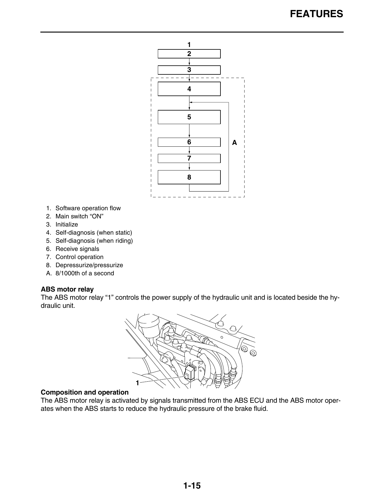
1. Software operation flow
2. Main switch “ON”
3. Initialize
4. Self-diagnosis (when static)
5. Self-diagnosis (when riding)
6. Receive signals
7. Control operation
8. Depressurize/pressurize
A. 8/1000th of a second
ABS motor relay
The ABS motor relay “1” controls the power supply of the hydraulic unit and is located beside the hy-
draulic unit.
Composition and operation
The ABS motor relay is activated by signals transmitted from the ABS ECU and the ABS motor oper-
ates when the ABS starts to reduce the hydraulic pressure of the brake fluid.
1-15