Outline Of The ABS
Fragment manuala — str. 14–18
📋 Tekst do skopiowania / wyszukiwania
FEATURES
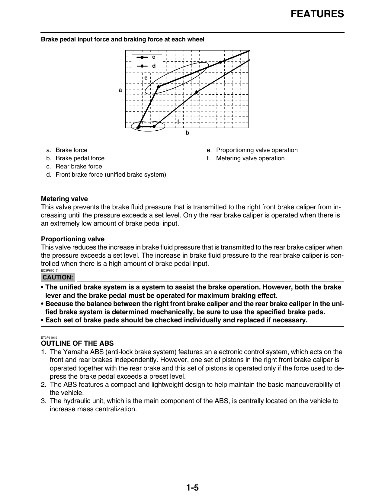
Brake pedal input force and braking force at each wheel
c
d
e
a
f
b
a. Brake force e. Proportioning valve operation
b. Brake pedal force f. Metering valve operation
c. Rear brake force
d. Front brake force (unified brake system)
Metering valve
This valve prevents the brake fluid pressure that is transmitted to the right front brake caliper from in-
creasing until the pressure exceeds a set level. Only the rear brake caliper is operated when there is
an extremely low amount of brake pedal input.
Proportioning valve
This valve reduces the increase in brake fluid pressure that is transmitted to the rear brake caliper when
the pressure exceeds a set level. The increase in brake fluid pressure to the rear brake caliper is con-
trolled when there is a high amount of brake pedal input.
EC3P61017
CAUTION:
• The unified brake system is a system to assist the brake operation. However, both the brake
lever and the brake pedal must be operated for maximum braking effect.
• Because the balance between the right front brake caliper and the rear brake caliper in the uni-
fied brake system is determined mechanically, be sure to use the specified brake pads.
• Each set of brake pads should be checked individually and replaced if necessary.
ET3P61019
OUTLINE OF THE ABS
1. The Yamaha ABS (anti-lock brake system) features an electronic control system, which acts on the
front and rear brakes independently. However, one set of pistons in the right front brake caliper is
operated together with the rear brake and this set of pistons is operated only if the force used to de-
press the brake pedal exceeds a preset level.
2. The ABS features a compact and lightweight design to help maintain the basic maneuverability of
the vehicle.
3. The hydraulic unit, which is the main component of the ABS, is centrally located on the vehicle to
increase mass centralization.
1-5
FEATURES
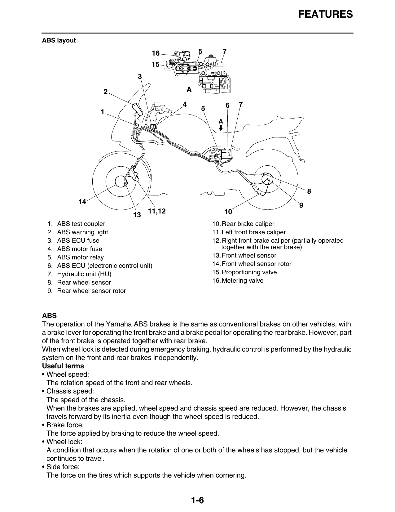
ABS layout
16 5 7
2 A
4 6 7
1 5
A
14 9
11,12 10
1. ABS test coupler 10. Rear brake caliper
2. ABS warning light 11. Left front brake caliper
3. ABS ECU fuse 12. Right front brake caliper (partially operated
4. ABS motor fuse together with the rear brake)
5. ABS motor relay 13. Front wheel sensor
6. ABS ECU (electronic control unit) 14. Front wheel sensor rotor
7. Hydraulic unit (HU) 15. Proportioning valve
8. Rear wheel sensor 16. Metering valve
9. Rear wheel sensor rotor
ABS
The operation of the Yamaha ABS brakes is the same as conventional brakes on other vehicles, with
a brake lever for operating the front brake and a brake pedal for operating the rear brake. However, part
of the front brake is operated together with rear brake.
When wheel lock is detected during emergency braking, hydraulic control is performed by the hydraulic
system on the front and rear brakes independently.
Useful terms
• Wheel speed:
The rotation speed of the front and rear wheels.
• Chassis speed:
The speed of the chassis.
When the brakes are applied, wheel speed and chassis speed are reduced. However, the chassis
travels forward by its inertia even though the wheel speed is reduced.
• Brake force:
The force applied by braking to reduce the wheel speed.
• Wheel lock:
A condition that occurs when the rotation of one or both of the wheels has stopped, but the vehicle
continues to travel.
• Side force:
The force on the tires which supports the vehicle when cornering.
1-6
FEATURES
• Slip ratio:
When the brakes are applied, slipping occurs between the tires and the road surface. This causes a
difference between the wheel speed and the chassis speed.
Slip ratio is the value that shows the rate of wheel slippage and is defined by the following formula.
Chassis speed –
Slip ratio = Wheel speed × 100 (%)
Chassis speed
0%: There is no slipping between the wheel and the road surface. The chassis speed is equal to the
wheel speed.
100%: The wheel speed is “0”, but the chassis is moving (i.e., wheel lock).
Brake force and vehicle stability
When the brake pressure is increased, wheel speed is reduced. Slipping occurs between the tire and
the road surface and brake force is generated. The limit of this brake force is determined by the friction
force between the tire and the road surface and is closely related to wheel slippage. Wheel slippage is
represented by the slip ratio.
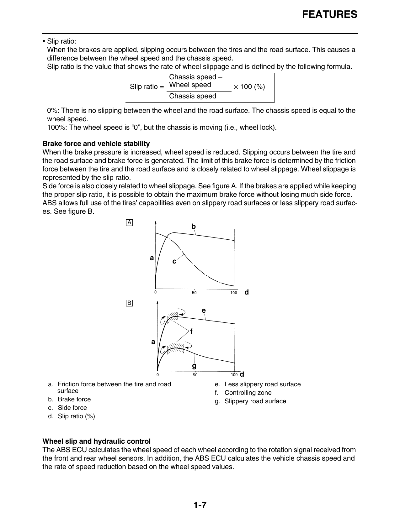
Side force is also closely related to wheel slippage. See figure A. If the brakes are applied while keeping
the proper slip ratio, it is possible to obtain the maximum brake force without losing much side force.
ABS allows full use of the tires’ capabilities even on slippery road surfaces or less slippery road surfac-
es. See figure B.
A
b
a
c
d
B
e
f
a
g
d
a. Friction force between the tire and road e. Less slippery road surface
surface f. Controlling zone
b. Brake force g. Slippery road surface
c. Side force
d. Slip ratio (%)
Wheel slip and hydraulic control
The ABS ECU calculates the wheel speed of each wheel according to the rotation signal received from
the front and rear wheel sensors. In addition, the ABS ECU calculates the vehicle chassis speed and
the rate of speed reduction based on the wheel speed values.
1-7
FEATURES
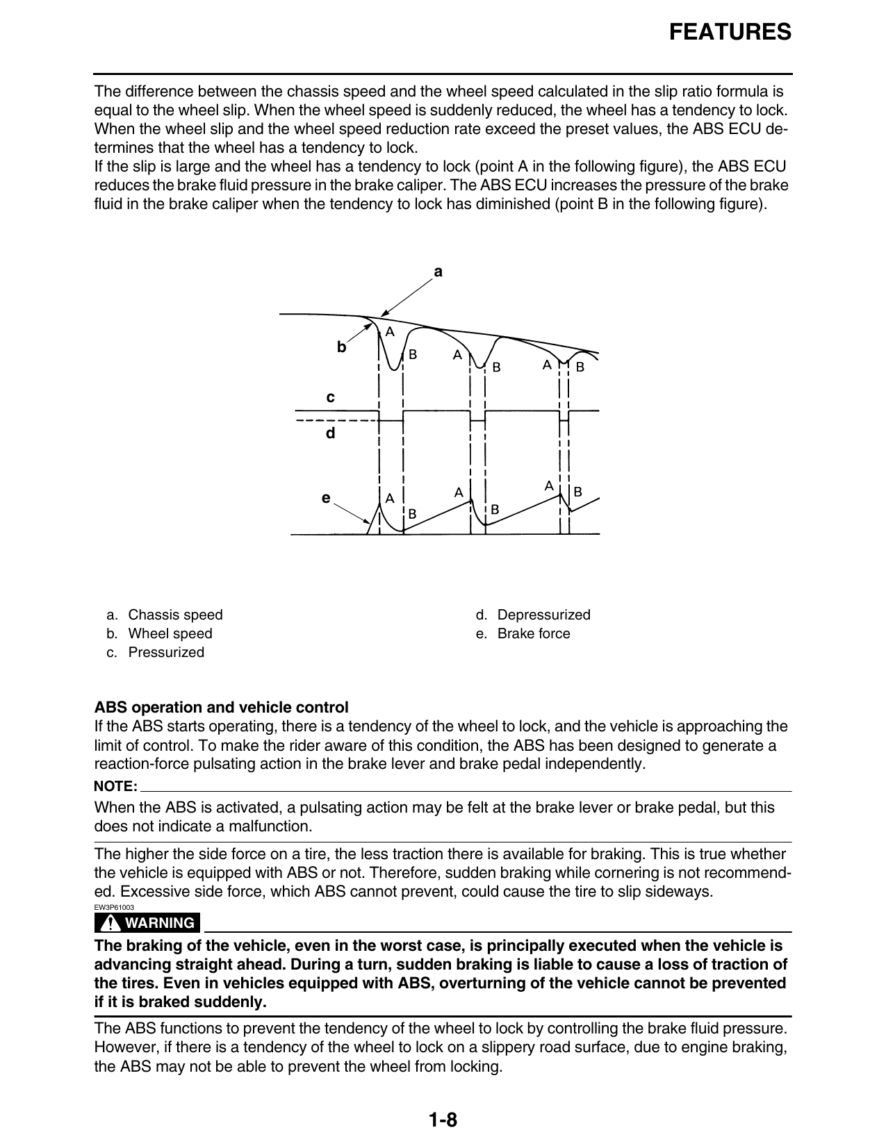
The difference between the chassis speed and the wheel speed calculated in the slip ratio formula is
equal to the wheel slip. When the wheel speed is suddenly reduced, the wheel has a tendency to lock.
When the wheel slip and the wheel speed reduction rate exceed the preset values, the ABS ECU de-
termines that the wheel has a tendency to lock.
If the slip is large and the wheel has a tendency to lock (point A in the following figure), the ABS ECU
reduces the brake fluid pressure in the brake caliper. The ABS ECU increases the pressure of the brake
fluid in the brake caliper when the tendency to lock has diminished (point B in the following figure).
a
b
c
d
e
a. Chassis speed d. Depressurized
b. Wheel speed e. Brake force
c. Pressurized
ABS operation and vehicle control
If the ABS starts operating, there is a tendency of the wheel to lock, and the vehicle is approaching the
limit of control. To make the rider aware of this condition, the ABS has been designed to generate a
reaction-force pulsating action in the brake lever and brake pedal independently.
NOTE:
When the ABS is activated, a pulsating action may be felt at the brake lever or brake pedal, but this
does not indicate a malfunction.
The higher the side force on a tire, the less traction there is available for braking. This is true whether
the vehicle is equipped with ABS or not. Therefore, sudden braking while cornering is not recommend-
ed. Excessive side force, which ABS cannot prevent, could cause the tire to slip sideways.
EW3P61003
WARNING
The braking of the vehicle, even in the worst case, is principally executed when the vehicle is
advancing straight ahead. During a turn, sudden braking is liable to cause a loss of traction of
the tires. Even in vehicles equipped with ABS, overturning of the vehicle cannot be prevented
if it is braked suddenly.
The ABS functions to prevent the tendency of the wheel to lock by controlling the brake fluid pressure.
However, if there is a tendency of the wheel to lock on a slippery road surface, due to engine braking,
the ABS may not be able to prevent the wheel from locking.
1-8
FEATURES
EWA13870
WARNING
The ABS controls only the tendency of the wheel to lock caused by applying the brakes. The
ABS cannot prevent wheel lock on slippery surfaces, such as ice, when it is caused by engine
braking, even if the ABS is operating.
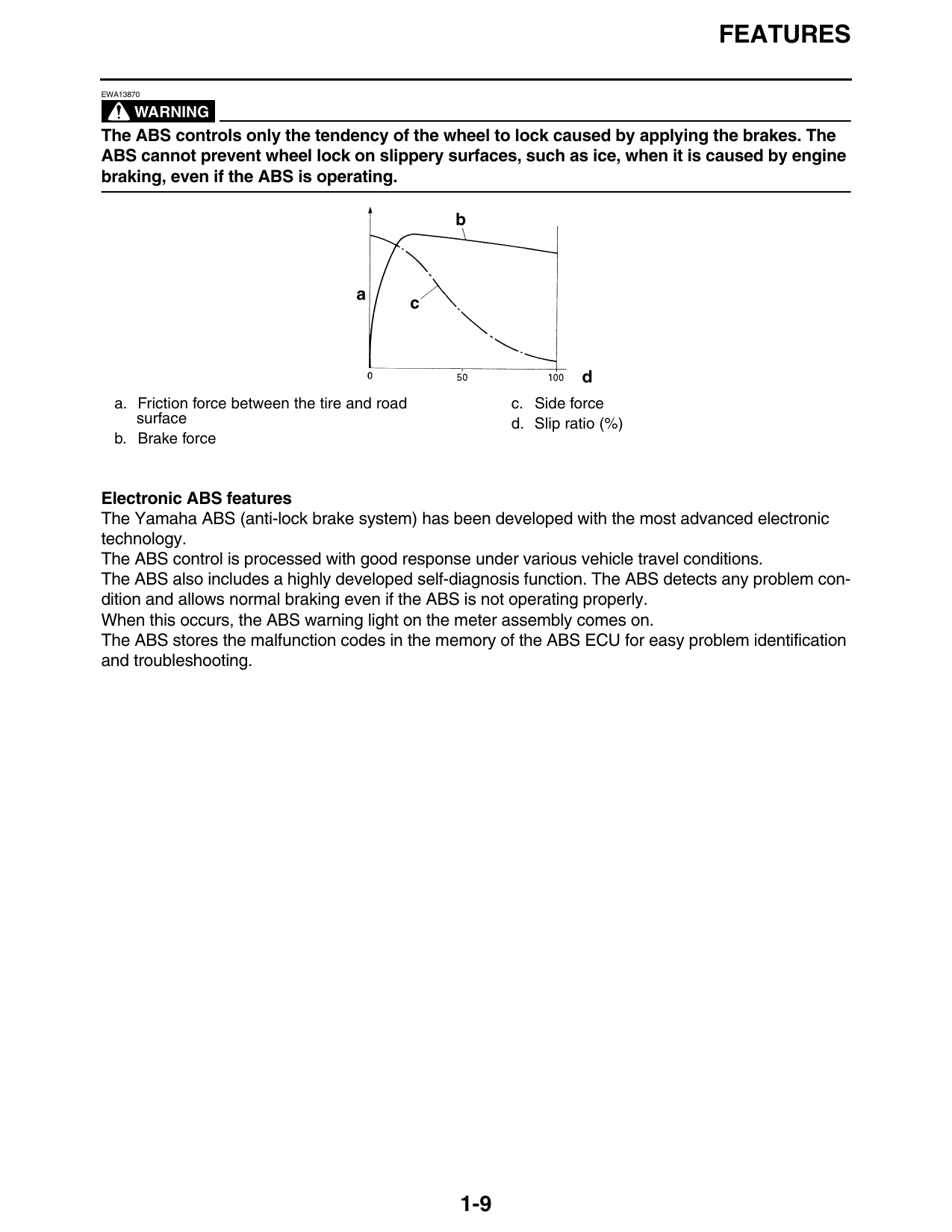
a. Friction force between the tire and road c. Side force
surface d. Slip ratio (%)
b. Brake force
Electronic ABS features
The Yamaha ABS (anti-lock brake system) has been developed with the most advanced electronic
technology.
The ABS control is processed with good response under various vehicle travel conditions.
The ABS also includes a highly developed self-diagnosis function. The ABS detects any problem con-
dition and allows normal braking even if the ABS is not operating properly.
When this occurs, the ABS warning light on the meter assembly comes on.
The ABS stores the malfunction codes in the memory of the ABS ECU for easy problem identification
and troubleshooting.
1-9