Cable Routing (FJR13AE)
Fragment manuala — str. 116–136
📋 Tekst do skopiowania / wyszukiwania
CABLE ROUTING (FJR13AE)
ET3P66048
CABLE ROUTING (FJR13AE)
3 B
2 A
L
23 22 C E
K 6
20 21 J 7
3 1
D
19 A
17 F 2
F
I
G
G
12 11 10 H 9 8
14 13
23 22
B-B
3 22 23
M 2
B
7 13
B
A
2-67
CABLE ROUTING (FJR13AE)
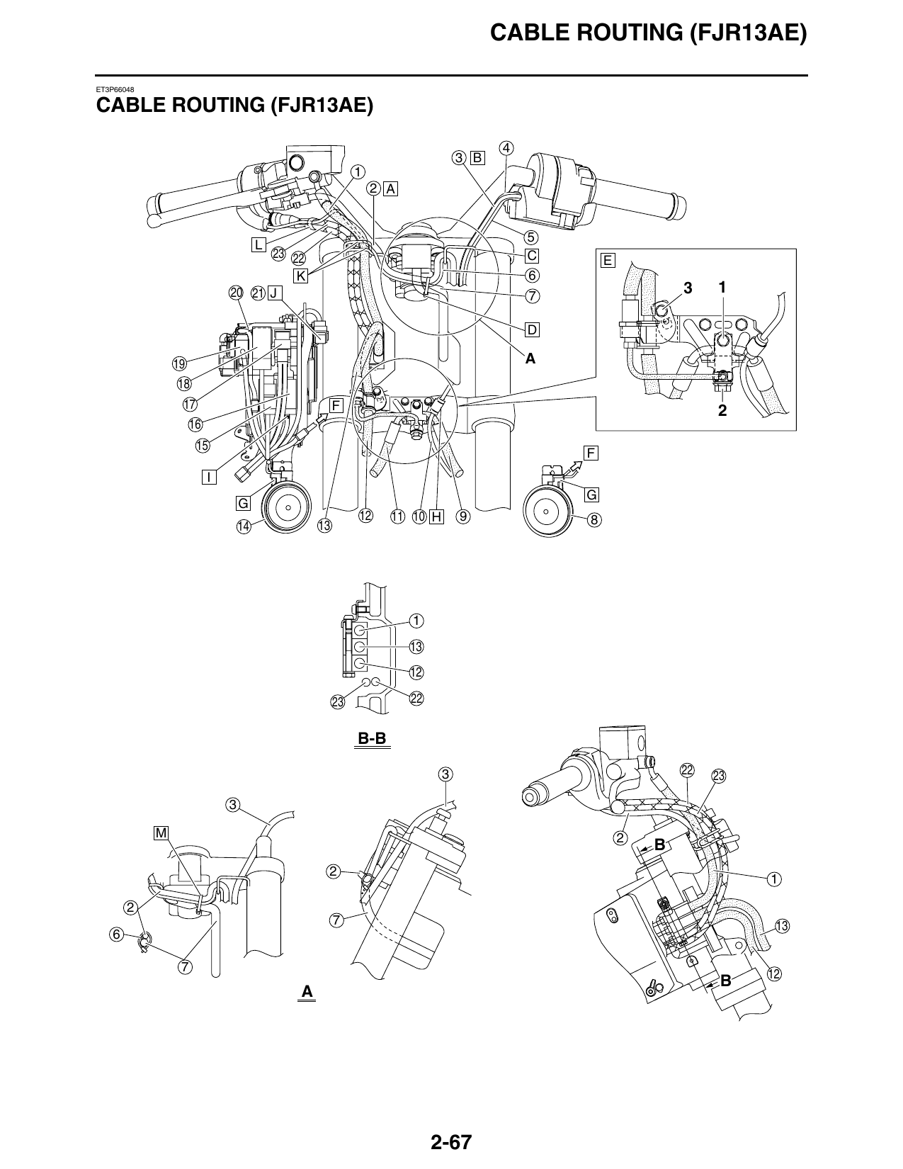
1. Brake hose (front brake master cylinder to M. Fasten the right handlebar switch lead, right grip
hydraulic unit) warmer lead, and main switch lead with a plastic
2. Right handlebar switch lead locking tie at the location shown in the illustration.
Position the buckle of the plastic locking tie under
3. Left handlebar switch lead the leads, with the end facing inward, and then cut
4. Left grip warmer lead off the excess end of the tie.
5. Hand shift switch lead
6. Right grip warmer lead
7. Main switch lead
8. Left horn (low)
9. Brake hose (hydraulic unit to left front brake
caliper)
10. Front wheel sensor lead
11. Brake hose (hydraulic unit to right front brake
caliper)
12. Brake hose (metering valve to right front brake
caliper)
13. Brake hose (hydraulic unit to front brake calipers)
14. Right horn (high)
15. Headlight (on/off)/grip warmer relay
16. Radiator fan motor relay
17. Main fuse
18. Brake light relay
19. YCC-S control relay
20. Positive battery lead
21. ABS test coupler
22. Throttle cable (accelerator cable)
23. Throttle cable (decelerator cable)
A. Route the right handlebar switch lead and right
grip warmer lead under the handlebar.
B. Route the left handlebar switch lead, left grip
warmer lead, and hand shift switch lead under the
handlebar.
C. Pass the hand shift switch lead, right grip warmer
lead, left grip warmer lead, right handlebar switch
lead, and left handlebar switch lead through the
guide.
D. Fasten the right handlebar switch lead, right grip
warmer lead, and main switch lead with a plastic
locking tie.
E. Temporarily tighten the brake hose joint bolt, union
bolt, and brake hose holder bolt in the proper
tightening sequence as shown. Then, tighten the
bolts to the specified torque, making sure to tighten
the brake hose joint bolt “1” last.
F. To front cowling wire harness
G. Install the horn L-shaped connectors so that the
leads are routed outward.
H. Fasten the grommet on the front wheel sensor lead
with the holder.
I. Connect the coupler that has blue tape wrapped
around its leads to the radiator fan motor relay.
J. Install the ABS test coupler completely onto the
tab on the battery stay.
K. Pass the brake hose (front brake master cylinder to
hydraulic unit), right handlebar switch lead, right
grip warmer lead, and throttle cables through the
guide as shown in the illustration.
L. Fasten the right grip warmer lead to the throttle
cables with a plastic locking tie 10 mm (0.39 in) or
less from the end of the throttle cable boot. Face
the end of the plastic locking tie upward or
downward, and then cut off the excess end of the
tie.
2-68
CABLE ROUTING (FJR13AE)
R
18 5 18 18
5 3
Q 5
13 5
C-C 27
30 27 30
18 D-D E-E
40 O
S
F
P 41 42
B-B 14 15
D
5 18
19 E
N 20
13 21 F
4 12 22
39 10 23
9 24
C 7
B 6
A-A 5
G
4 CB D E
3 B 26
H
1 A 28
A 27
C 29
D K E
A J I
L F
35 34
M
2-69
CABLE ROUTING (FJR13AE)
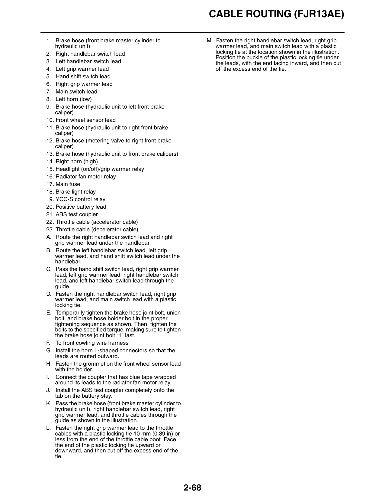
1. O2 sensor lead F. Route the positive battery lead between the
battery stay and the battery box.
2. Engine idling speed adjusting cable
G. To front cowling wire harness
3. Starter motor lead
H. Align the rear end of the right radiator fan motor
4. Air deflector coupler with the tape on the wire harness as
5. Wire harness shown in the illustration.
6. Spark plug lead #4 I. Fasten the wire harness, right horn (high) leads,
7. Spark plug lead #1 and right radiator fan motor lead with a plastic
locking tie, making sure to install the tie on the fan
8. Cylinders-#1/#4 ignition coil motor lead’s protective sleeve. Face the end of the
9. Cylinders-#2/#3 ignition coil plastic locking tie outward. Do not cut off the
10. Starter relay excess end of the plastic locking tie.
11. Starter relay lead J. To front right turn signal light
12. Fuse box 2 K. Fasten the wire harness, right radiator fan motor
lead, negative battery lead, and starter motor lead
13. Negative battery lead to the battery stay with a plastic locking tie, making
14. Brake hose (front brake master cylinder to sure to install the tie on the fan motor lead’s
hydraulic unit) protective sleeve and to position the tie in front of
15. Right handlebar switch lead the air deflector. Face the end of the plastic locking
tie outward, and then cut off the excess end of the
16. Throttle cable (accelerator cable) tie.
17. Throttle cable (decelerator cable) L. Fasten the wire harness to the battery stay with a
18. Battery stay plastic locking tie. Face the end of the plastic
19. Battery locking tie upward, and then cut off the excess end
of the tie.
20. Positive battery lead
M. Fasten the negative battery lead at the blue tape,
21. Main fuse starter motor lead, and water pump breather hose
22. YCC-S control relay with a plastic locking tie, making sure to install the
23. Brake light relay tie around the end of the hose’s protective sleeve,
and then cut off the excess end of the tie. Do not
24. Headlight (on/off)/grip warmer relay kink the water pump breather hose and do not face
25. Front cowling wire harness the end of the plastic locking tie downward.
26. Radiator fan motor relay N. Route the wire harness to the outside of the spark
27. Right horn (high) leads plug leads.
28. Positive battery lead coupler O. Route the ignition coil primary leads to the inside
of the fuse box leads.
29. Front right turn signal light lead
P. Route the fuse box leads, starter relay lead, and
30. Right radiator fan motor lead ignition coil primary leads between the battery stay
31. Ground lead coupler and the guide.
32. Brake hose (hydraulic unit to right front brake Q. Make sure that the wire harness does not protrude
caliper) to the outside of the battery stay.
33. Brake hose (metering valve to right front brake R. Pass the plastic locking tie between the guide and
caliper) the wire harness.
34. Right horn (high) S. Position the plastic locking tie to the rear of the
35. Right horn (high) connectors bend in the battery stay.
36. Water pump breather hose
37. Right radiator fan
38. Crankshaft position sensor lead
39. Spark plug leads
40. Ignition coil primary leads
41. Fuse box leads
42. Guide
A. Route the O2 sensor lead to the inside of the
engine idling speed adjusting cable.
B. Make sure that the wire harness and spark plug
leads are positioned in the indentation on the right
side of the air deflector.
C. Route the spark plug leads to the inside of the
battery stay pipe.
D. Fasten the negative battery lead at the blue tape
and the starter motor lead to the battery box with a
plastic locking tie. Face the end of the plastic
locking tie downward. Do not cut off the excess
end of the plastic locking tie.
E. Fasten the negative battery lead and starter motor
lead to the battery box with a plastic locking tie.
Face the end of the plastic locking tie rearward. Do
not cut off the excess end of the plastic locking tie.
2-70
CABLE ROUTING (FJR13AE)
2 3 D 4 5 6 7 8 9
E
1 A
B F
C
15 G 14 13
2-71
CABLE ROUTING (FJR13AE)
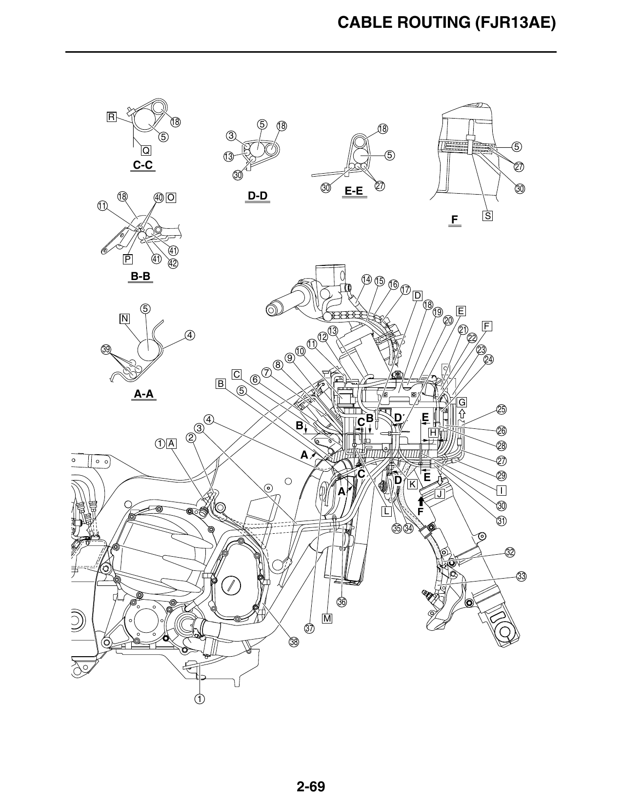
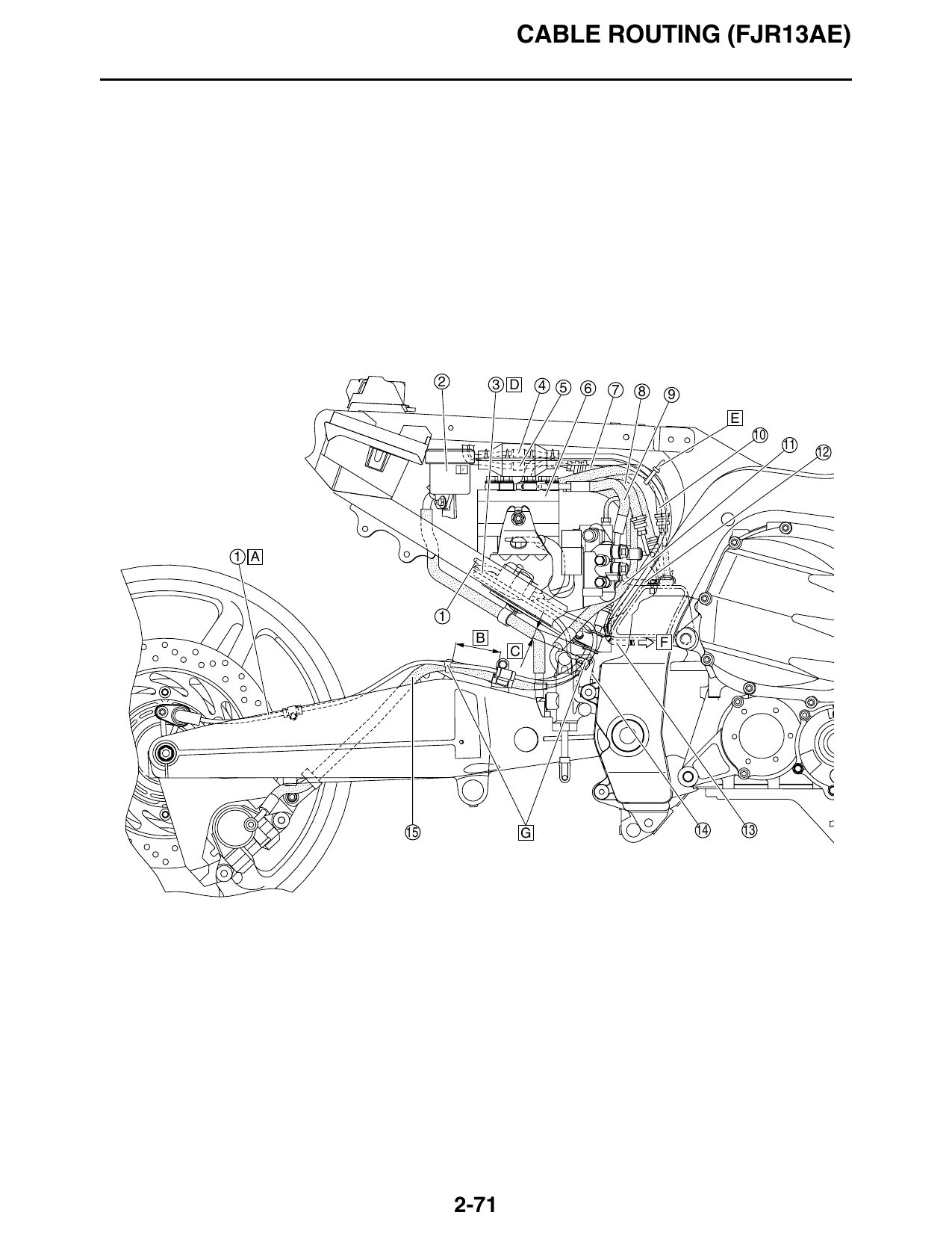
1. Rear wheel sensor lead
2. Rear brake fluid reservoir
3. Rear brake light switch lead
4. Clutch actuator motor lead
5. Clutch actuator sensor lead
6. Hydraulic unit
7. Brake hose (front brake master cylinder to
hydraulic unit)
8. Brake hose (hydraulic unit to proportioning valve)
9. Brake hose (hydraulic unit to metering valve)
10. Brake hose (hydraulic unit to front brake calipers)
11. Brake hose (rear brake master cylinder to
hydraulic unit)
12. Brake pipe (metering valve to right front brake
caliper)
13. Clutch hose
14. Rear brake light switch
15. Brake hose (proportioning valve to rear brake
caliper)
A. Route the rear wheel sensor lead to the inside of
the swingarm, making sure that the lead does not
protrude above the swingarm.
B. 45–55 mm (1.77–2.17 in)
C. 10–20 mm (0.39–0.79 in)
D. Route the rear brake light switch lead under the
rear wheel sensor lead.
E. Fasten the clutch actuator motor lead and clutch
actuator sensor lead to the brake hose (hydraulic
unit to front brake calipers) with the plastic locking
tie, making sure to face the end of the tie forward.
Do not cut off the excess end of the plastic locking
tie.
F. To clutch actuator
G. Fasten the rear wheel sensor lead to the brake
hose (proportioning valve to rear brake caliper)
with the two holders, making sure that the fastener
of each holder faces inward.
2-72
CABLE ROUTING (FJR13AE)
1 A 2 B 3 4 6
C
D
E
2-73
CABLE ROUTING (FJR13AE)
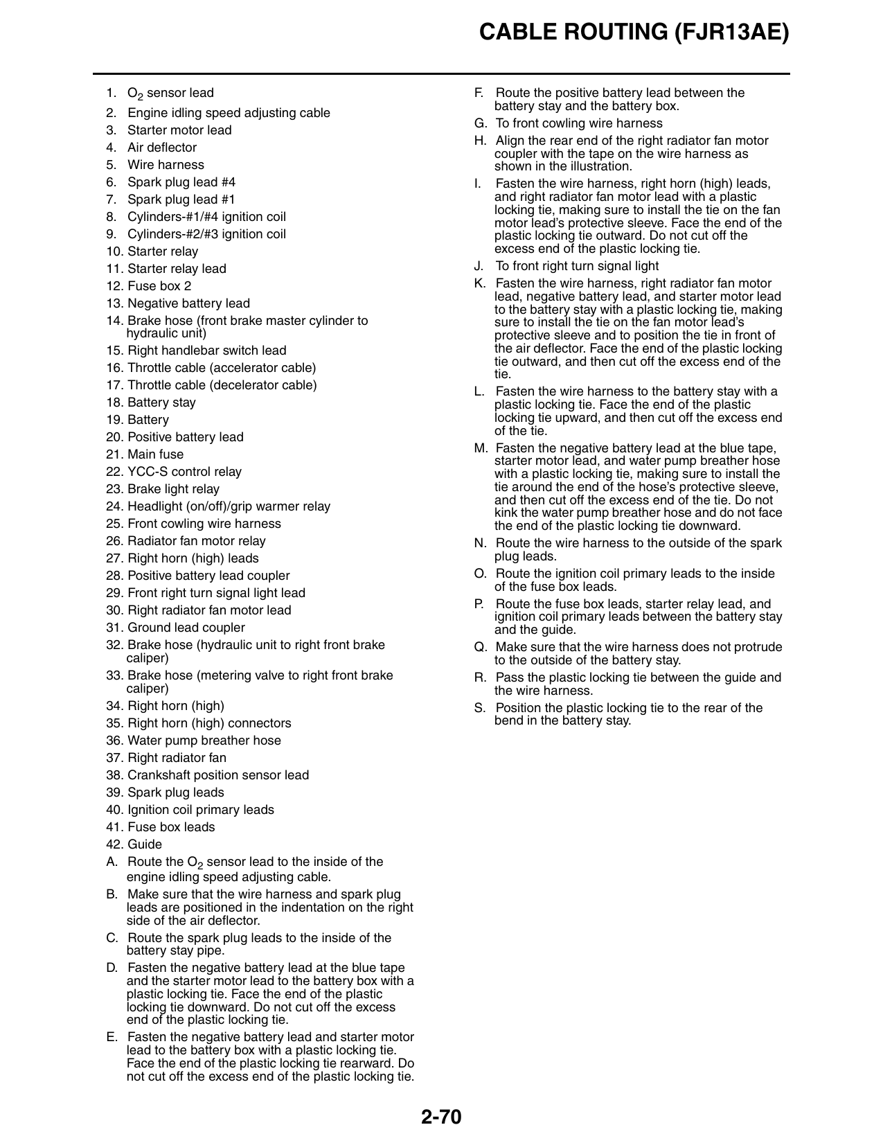
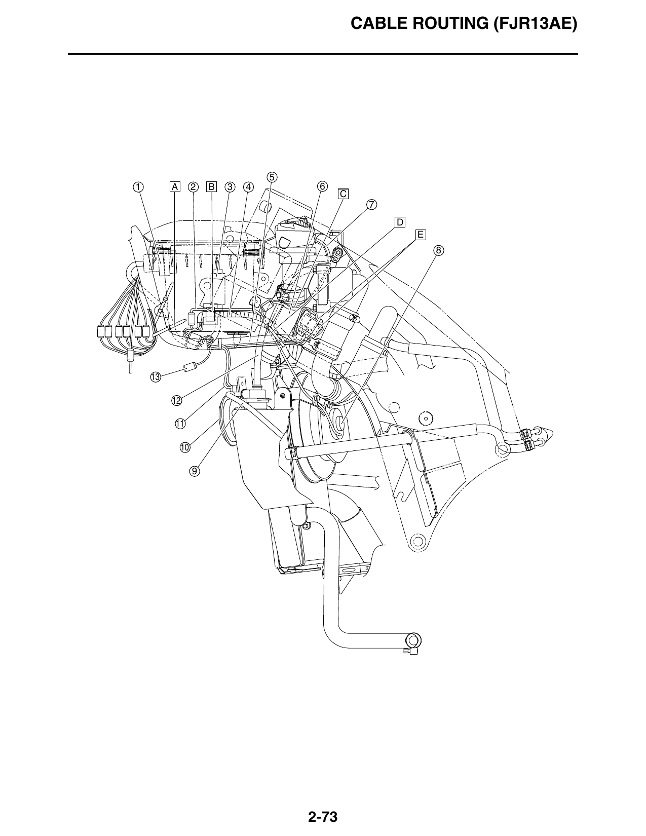
1. Auxiliary DC jack
2. Left radiator fan motor lead
3. Accessory box solenoid
4. Wire harness
5. Front cowling wire harness
6. Radiator inlet hose
7. Grip warmer control unit leads
8. Left radiator fan
9. Coolant reservoir breather hose
10. Left horn (low)
11. Left horn (low) leads
12. Thermostat assembly breather hose
13. Joint coupler
A. Fasten the handlebar switch leads, hand shift
switch lead, and grip warmer leads to the front
cowling wire harness with a plastic locking tie.
Face the end of the plastic locking tie rearward,
along the side of the accessory box. Do not cut off
the excess end of the plastic locking tie.
B. Fasten the wire harness and left radiator fan motor
lead with the holder.
C. Route the grip warmer control unit leads to the
outside of the thermostat assembly breather hose.
D. Fasten the front cowling wire harness to the
radiator inlet hose with a plastic locking tie, making
sure to install the tie on the harness’ protective
sleeve, and then cut off the excess end of the tie.
E. After connecting the couplers, cover them
completely with the cover, and then push them in
between the radiator inlet hose and the thermostat
inlet hose 2.
2-74
CABLE ROUTING (FJR13AE)
34 35
33 36
32 37 38
A-A UP
D 39
17 U C
6 7 8 9
4 V
W
X 20
B 41 36 Y 40
A
B
D
C
D 11 E
12 13
N F
30 A
B
T
29 S A
O
R
27 C
Q P 26
M
28 22 14
25 L K 15 16
G
24 J 19 18 17 I H
2-75
CABLE ROUTING (FJR13AE)
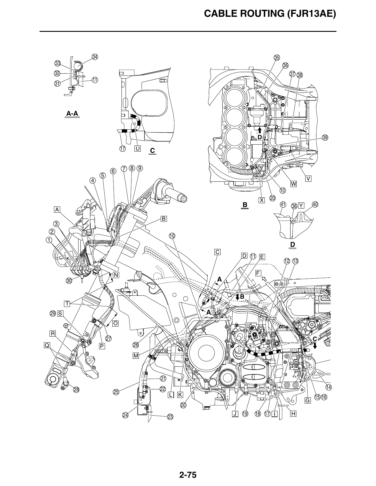
1. Grip warmer couplers C. To oil level switch
2. Hand shift switch coupler D. Fasten the leads (to oil level switch and crankshaft
3. Handlebar switch couplers position sensor) that branch off from the wire
harness to the guide on the holder with a plastic
4. Right grip warmer lead locking tie, making sure that the end of the tie faces
5. Right handlebar switch lead upward. Do not cut off the excess end of the plastic
6. Main switch lead locking tie.
7. Hand shift switch lead E. Fasten the sidestand switch lead, stator coil lead,
and oil level switch lead with a plastic locking tie,
8. Left grip warmer lead making sure to bundle and fasten the sidestand
9. Left handlebar switch lead switch lead so that the coupler is positioned to the
10. Stator coil lead front of the tie. Face the end of the plastic locking
tie outward. Do not cut off the excess end of the
11. Fuel tank breather hose (joint to rollover valve) (for plastic locking tie.
California only)
F. To fuel tank
12. Air filter case breather hose
G. Pass the fuel tank breather/overflow hose through
13. Gear position sensor lead the guide on the universal joint dust cover.
14. Foot shift switch lead H. Pass the air filter case breather hose through the
15. Fuel tank breather/overflow hose (except for guide on the muffler bracket.
California) I. Fasten the clutch hose with the pivot shaft locknut
16. Fuel tank overflow hose (for California only) retainer.
17. Clutch hose J. Pass the fuel tank breather hose (joint to rollover
18. Sidestand switch valve) between the frame and the projection on the
air filter case as shown in the illustration. (for
19. Sidestand switch lead California only)
20. Oil level switch lead K. Pass the canister purge hose (3-way joint to
21. Rollover valve (for California only) canister) through the opening in the frame, to the
22. Fuel tank breather hose (rollover valve to canister) inside of the frame. (for California only)
(for California only) L. Pass the fuel tank breather hose (joint to rollover
23. Canister breather hose (for California only) valve) through the cutout in the air deflector. (for
California only)
24. Canister (for California only)
M. Route the coolant reservoir breather hose to the
25. Canister purge hose (3-way joint to canister) (for outside of the fuel tank breather hose (joint to
California only) rollover valve) and the canister purge hose (3-way
26. Coolant reservoir breather hose joint to canister). (for California only)
27. Brake hose (hydraulic unit to left front brake caliper) N. 43–53 mm (1.69–2.09 in)
28. Front wheel sensor O. 60–70 mm (2.36–2.76 in)
29. Front wheel sensor lead P. Fasten the grommets on the front wheel sensor
30. Front left turn signal light lead lead and the brake hose (hydraulic unit to left front
31. Brake pipe (metering valve to right front brake brake caliper) with the holder.
caliper) Q. Route the front wheel sensor lead to the outside of
32. Brake pipe (hydraulic unit to front brake calipers) the left front brake caliper lower mounting boss and
the boss for the left front fork compression
33. Brake pipe (front brake master cylinder to hydraulic damping force adjusting screw.
unit)
R. Fasten the grommet on the front wheel sensor lead
34. Wire harness with the holder.
35. Crankshaft position sensor lead S. Route the front wheel sensor lead between the left
36. Starter motor lead front brake caliper and the brake hose (hydraulic
37. Neutral switch coupler unit to left front brake caliper).
38. YCC-S speed sensor T. Fasten the front wheel sensor lead to the brake
hose (hydraulic unit to left front brake caliper) with
39. Oil level switch coupler the two holders, making sure to position the lead to
40. Upper crankcase the inside of the hose.
41. Rear balancer cover U. Route the fuel tank breather/overflow hose to the
A. Secure the plastic band by inserting the projection front of the clutch hose, then through the opening
on the band into the hole in the windshield drive between the frame and the swingarm.
unit/meter assembly stay, and then fasten the V. Face the ends of the clamp to the left, making sure
handlebar switch leads, grip warmer leads and that the lower end contacts the wire harness.
hand shift switch lead with the band, making sure W. Fasten the oil level switch lead and starter motor
that the end of the band faces down. Do not cut off lead with the clamp.
the excess end of the plastic band.
X. To sidestand switch
B. Secure the plastic band by inserting the projection
on the band into the hole in the windshield drive Y. Route the starter motor lead between the rear
unit/meter assembly stay, and then fasten the balancer cover bolt and the rib on the crankcase.
handlebar switch leads, grip warmer leads, hand
shift switch lead and front wheel sensor lead with
the band, making sure that the end of the band
faces down. Do not cut off the excess end of the
plastic band.
2-76
CABLE ROUTING (FJR13AE)
11 22 3 H
27 23
26 B-B
24 G
A-A
C
1 2 3 4
8 A
B
B
A A 9
C
D
B 13
14 5 J K
I L
16 E 6
F 19 18
C 5 M
2-77
CABLE ROUTING (FJR13AE)
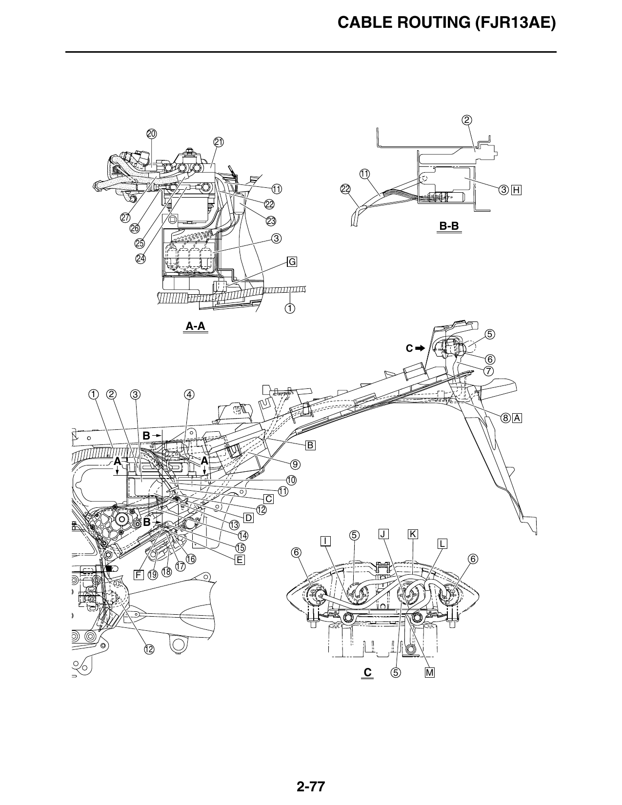
1. Wire harness L. Route the leads between the left tail/brake light
2. ECU (engine control unit) bulb socket and the rear left turn signal light bulb
socket.
3. ABS ECU (electronic control unit)
M. Route the tail/brake light assembly lead between
4. MCU (motor control unit) the tail/brake light assembly and its bracket.
5. Tail/brake light
6. Rear turn signal light
7. Tail/brake light assembly lead
8. License plate light lead
9. Seat lock cable
10. Shift actuator motor lead
11. ABS wire harness
12. Foot shift switch lead
13. Clutch fluid reservoir hose
14. Shift actuator sensor lead
15. Hydraulic unit breather hose
16. Stator coil lead
17. Rear shock absorber spring preload adjusting
cable
18. Rectifier/regulator
19. Rectifier/regulator lead
20. Brake hose (hydraulic unit to metering valve)
21. Hydraulic unit
22. Rear wheel sensor lead
23. Rear brake light switch lead
24. Brake hose (front brake master cylinder to
hydraulic unit)
25. Brake hose (hydraulic unit to front brake calipers)
26. Brake hose (rear brake master cylinder to
hydraulic unit)
27. Brake hose (hydraulic unit to proportioning valve)
A. Pass the license plate light lead through the hole in
the rear fender.
B. Route the wire harness to the inside of the seat
lock cable.
C. Fasten the shift actuator motor lead, shift actuator
sensor lead, and foot shift switch lead to the ABS
wire harness with a plastic locking tie, making sure
to position the harness to the outside of the other
leads. Face the end of the plastic locking tie
inward, without cutting off the excess end.
D. Fasten the ABS wire harness with the holder.
E. Route the stator coil lead and rectifier/regulator
lead to the outside of the rear shock absorber
spring preload adjusting cable and under the
hydraulic unit breather hose and clutch fluid
reservoir hose.
F. Pass the stator coil lead, rectifier/regulator lead,
and hydraulic unit breather hose through the guide
on the frame, making sure to route the hose to the
outside of the leads.
G. Fasten the leads (to ABS wire harness and rear
brake light switch) that branch off from the wire
harness with the holder.
H. When installing the ABS ECU, be sure not to pinch
the rear wheel sensor lead and ABS wire harness
between the ABS ECU and the rear fender.
I. Route the rear right turn signal light lead under the
right tail/brake light bulb socket.
J. Route the tail/brake light assembly lead between
the left tail/brake light bulb socket and the
mounting boss on the tail/brake light assembly.
K. Route the rear right turn signal light lead and right
tail/brake light lead over the left tail/brake light bulb
socket.
2-78
CABLE ROUTING (FJR13AE)
3 4 5 6 7 8 C
2 A
1 17
B
D
N
E
F
F
31 M 22
30 L G
K
J
29 26
28 I H
2-79
CABLE ROUTING (FJR13AE)
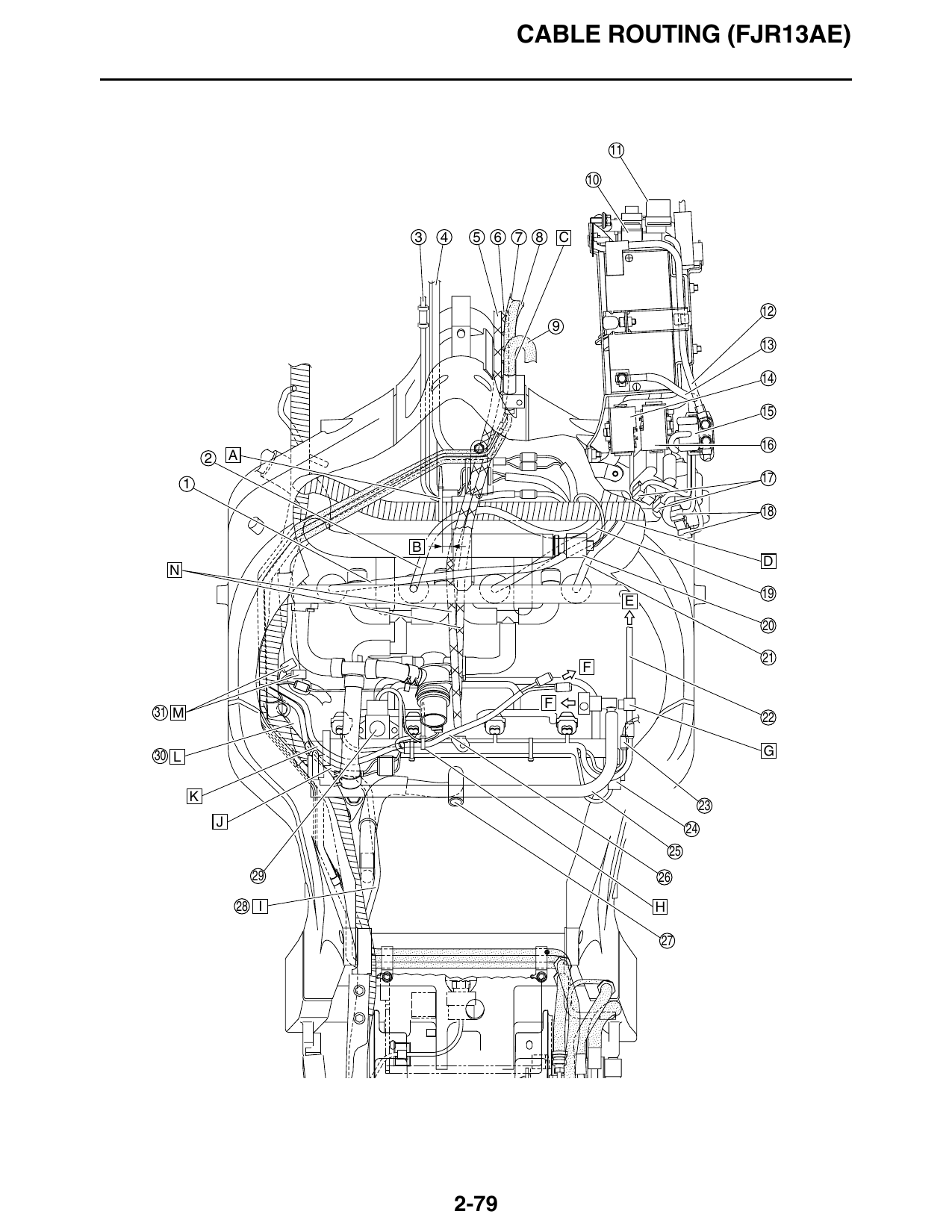
1. Spark plug lead #1 L. Route the fuel tank breather hose (joint to rollover
2. Spark plug lead #2 valve) next to the wire harness and pass it through
the guide. (for California only)
3. Front wheel sensor lead
M. Place the joint couplers in the area shown in the
4. Main switch lead illustration, making sure that they do not protrude
5. Throttle cable (accelerator cable) above the wire harness.
6. Throttle cable (decelerator cable) N. Route the throttle cables over the main switch lead,
7. Brake hose (hydraulic unit to front brake calipers) spark plug lead #2, and wire harness, and under
spark plug lead #1.
8. Brake hose (metering valve to right front brake
caliper)
9. Brake hose (front brake master cylinder to
hydraulic unit)
10. Main fuse
11. Brake light relay
12. Positive battery lead
13. Negative battery lead
14. Fuse box 1 (identified by blue tape on lead)
15. Starter relay
16. Fuse box 2
17. Cylinders-#2/#3 ignition coil connectors (white)
18. Cylinders-#1/#4 ignition coil connectors (black)
19. Spark plug lead #3
20. Coolant temperature sensor
21. Spark plug lead #4
22. Cylinder identification sensor lead
23. O2 sensor coupler
24. Throttle position sensor
25. Fuel hose
26. Fuel pump/fuel sender lead
27. Crankcase breather hose
28. Stator coil lead
29. Intake air pressure sensor
30. Fuel tank breather hose (joint to rollover valve) (for
California only)
31. Joint couplers
A. Fasten the front wheel sensor lead to the wire
harness with a plastic locking tie, making sure to
align the tie with the white tape on the harness.
Face the end of the plastic locking tie forward. Do
not cut off the excess end of the plastic locking tie.
B. Position the plastic locking tie 0–20 mm (0–0.79
in) from the end of the protective sleeve of the front
wheel sensor lead.
C. Route the throttle cables and brake hoses through
the right opening in the frame.
D. Route the wire harness over the spark plug leads.
E. To cylinder identification sensor
F. To fuel tank
G. Fasten the cylinder identification sensor lead with
the holder on the throttle body.
H. Fasten the fuel pump/fuel sender lead and air
induction system solenoid lead to sub-wire
harness with a plastic locking tie, making sure that
the end of the tie faces forward. Do not cut off the
excess end of the plastic locking tie.
I. Route the stator coil lead to the inside of the
engine bracket (top) and under the crankcase
breather hose.
J. Route the wire harness (to sub-wire harness)
under the fuel hose connector.
K. Route the fuel pump/fuel sender lead under the
fuel hose connector.
2-80
CABLE ROUTING (FJR13AE)
I
A
H 1
G
B
C
E
F
D
E 3
2-81
CABLE ROUTING (FJR13AE)
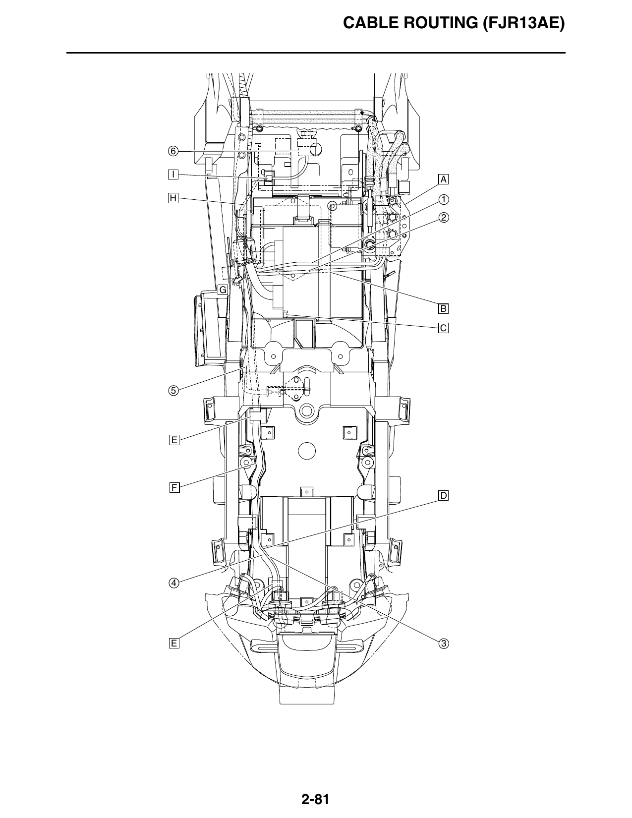
1. Clutch actuator motor lead
2. Clutch actuator sensor lead
3. License plate light lead
4. Tail/brake light assembly lead
5. Seat lock cable
6. Intake air temperature sensor
A. Connect the clutch actuator motor lead and clutch
actuator sensor lead, install the rubber cover
around the leads, and then place the cover
between the hydraulic unit and the frame. When
closing the rubber cover, make sure that the thick
section at the base of each projection (four
locations) on one side of the cover is pulled
through its corresponding hole on the other side.
Face the side of the rubber cover with the
projections outward.
B. Fasten the clutch actuator motor lead and clutch
actuator sensor lead with the band that is used to
secure the MCU (motor control unit).
C. Make sure that the projection on the storage
compartment fits into the indentation in the MCU
(motor control unit). The MCU should not be
resting on top of the projection.
D. Route the tail/brake light assembly lead and
license plate light lead between the rib and the U-
lock holder on the rear fender, making sure that the
leads are not routed on top of the holder.
E. Fasten the tail/brake light assembly lead and
license plate light lead with the holder.
F. Route the tail/brake light assembly lead and
license plate light lead between the ribs on the rear
fender.
G. To shift actuator
H. Route the intake air temperature sensor lead
under the wire harness.
I. Fasten the intake air temperature sensor lead to
the air filter case with the holder.
2-82
CABLE ROUTING (FJR13AE)
Q
R
A
A
C 2 B
3 4 E 5 F 6
D
15 P
A
14 7 G
12 O
H
N 11 L K J 10
M
9 I
2-83
CABLE ROUTING (FJR13AE)
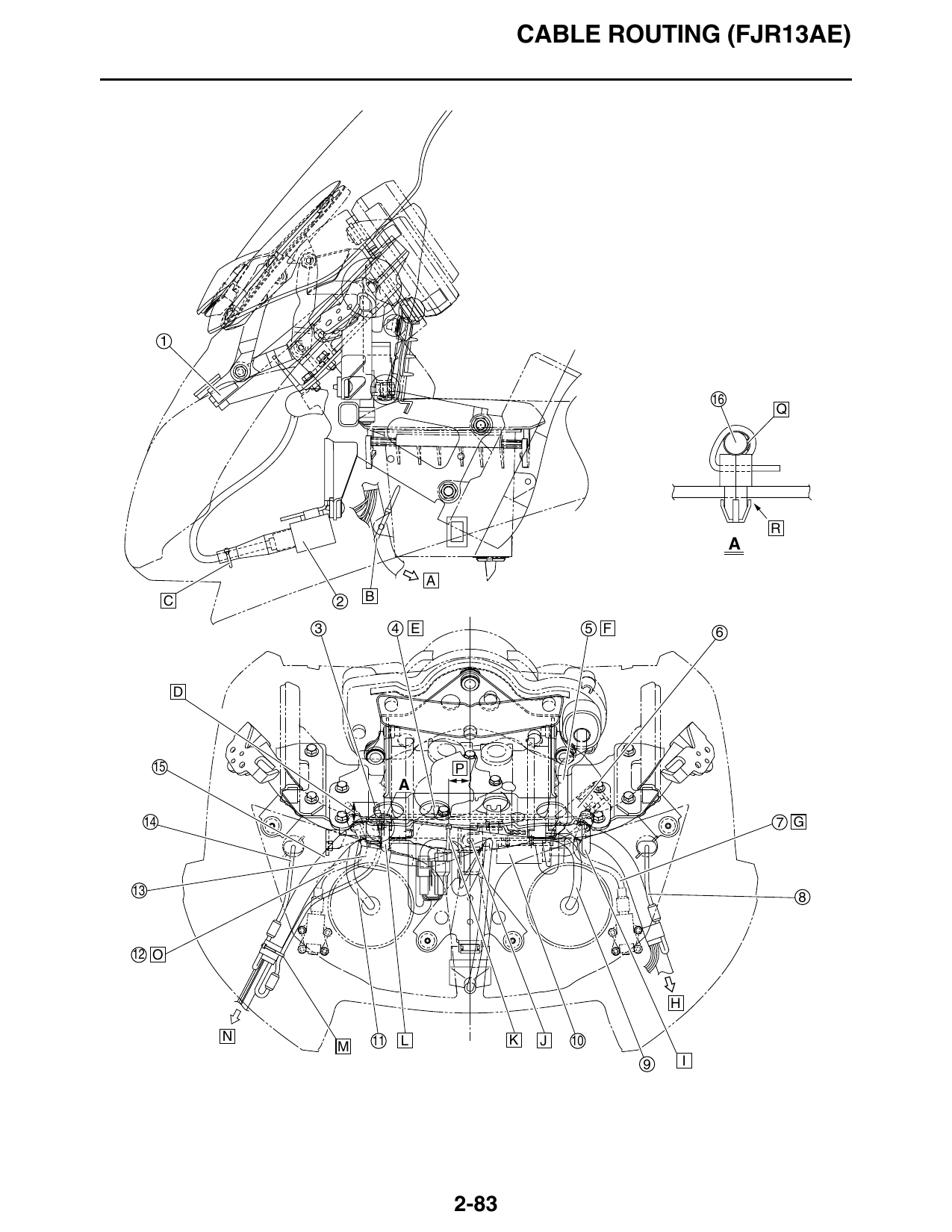
1. Windshield drive unit O. Route the right headlight beam adjusting cable
2. Relay unit between the right headlight lead and the thermistor
lead.
3. Thermistor
P. Position the plastic locking tie 25 mm (0.98 in) to
4. Windshield drive unit lead the right of the center of the front cowling as shown
5. Meter assembly lead in the illustration.
6. Headlight relay (dimmer) Q. Fasten the thermistor lead with a plastic locking tie,
7. Left headlight beam adjusting cable and then cut off the excess end of the tie. Be sure
to fold the protective sleeve against the lead to
8. Left auxiliary light lead remove any space between the sleeve and the
9. Left headlight lead lead when fastening it.
10. Lean angle sensor R. Secure the plastic locking tie by inserting the
11. Right headlight lead projection on the tie into the hole in the rear of the
windshield drive unit/meter assembly stay.
12. Right headlight beam adjusting cable
13. Turn signal/hazard relay
14. Right auxiliary light lead
15. Front cowling wire harness
16. Thermistor lead
A. To wire harness
B. Fasten the front cowling wire harness to the stay
on the accessory box with a plastic locking tie as
shown in the illustration, making sure to position
the tie below where the headlight leads branch off
from the harness. Face the end of the plastic
locking tie rearward, along the side of the
accessory box. Do not cut off the excess end of the
plastic locking tie.
C. Slide the boot over the relay unit coupler, and then
fasten the boot with a plastic locking tie. Cut off the
excess end of the plastic locking tie.
D. Less than 20 mm (0.79 in)
E. Pass the windshield drive unit lead through the
hole in the windshield drive unit/meter assembly
stay.
F. Route the meter assembly lead under the
windshield drive unit.
G. Route the left headlight beam adjusting cable
under the left headlight lead.
H. To wire harness
I. Secure the plastic band by inserting the projection
on the band into the hole in the front of the
windshield drive unit/meter assembly stay, and
then fasten the front cowling wire harness with the
band after the headlight lead branches off from the
harness.
J. Secure the front cowling wire harness at the
location shown in the illustration by inserting the
projection on its holder into the hole in the
windshield drive unit/meter assembly stay.
K. Fasten the leads (to windshield drive unit) that
branch off from the front cowling wire harness to
the harness with a plastic locking tie, making sure
to position the tie 20 mm (0.79 in) from the drive
unit couplers.
L. Secure the plastic band by inserting the projection
on the band into the hole in the front of the
windshield drive unit/meter assembly stay, and
then fasten the front cowling wire harness with the
band after the headlight lead branches off from the
harness.
M. Fasten the thermistor lead to the front cowling wire
harness with a plastic locking tie, making sure to
align the tie with the tape used to fasten the front
right turn signal light lead. The thermistor lead
should not be taut.
N. To front right turn signal light, right horn (high), and
wire harness
2-84
CABLE ROUTING (FJR13AE)
3 4 5 6 7
7 C
1 A 8
D
B
12 B
2 17
12 4
11 A 4
H I
10 3
A
14 15
16 E
17 J B
C C
4 3
G 16
1 C-C
G
F 6 11 8 5 10
2-85
CABLE ROUTING (FJR13AE)
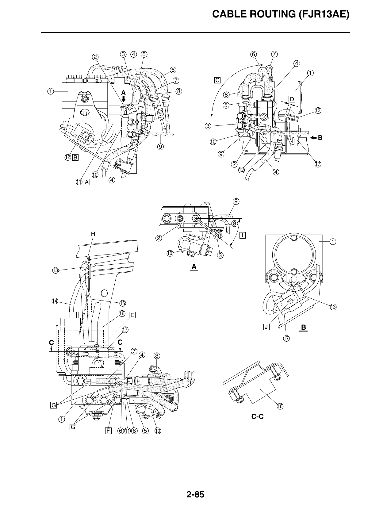
1. Hydraulic unit
2. Proportioning valve
3. Brake hose (proportioning valve to rear brake
caliper)
4. Brake hose (rear brake master cylinder to
hydraulic unit)
5. Brake hose (hydraulic unit to metering valve)
6. Brake hose (hydraulic unit to front brake calipers)
7. Brake hose (front brake master cylinder to
hydraulic unit)
8. Brake hose (hydraulic unit to proportioning valve)
9. Brake hose (metering valve to right front brake
caliper)
10. Metering valve
11. ABS motor relay
12. Hydraulic unit solenoid coupler
13. Hydraulic unit breather hose
14. Stator coil lead
15. Rectifier/regulator lead
16. Rectifier/regulator
17. ABS motor coupler
A. Install the ABS motor relay completely onto the tab
on the hydraulic unit bracket.
B. Install the hydraulic unit solenoid coupler
completely onto the tab on the hydraulic unit
bracket.
C. 87–93°
D. 5–7 mm (0.20–0.28 in)
E. Install the hydraulic unit breather hose so that the
white paint mark on the hose is facing down.
F. Make sure that the brake hose (hydraulic unit to
proportioning valve) contacts the end of the brake
hose (hydraulic unit to metering valve).
G. Make sure that the brake hoses contact the
stoppers on the hydraulic unit.
H. Pass the hydraulic unit breather hose, stator coil
lead, and rectifier/regulator lead though the guide.
I. 36–42°
J. Install the ABS motor coupler completely onto the
tab on the hydraulic unit bracket.
2-86
CABLE ROUTING (FJR13AE)
2-87