Lubrication Diagrams
Fragment manuala — str. 82–91
📋 Tekst do skopiowania / wyszukiwania
LUBRICATION SYSTEM CHART AND DIAGRAMS
EAS20410
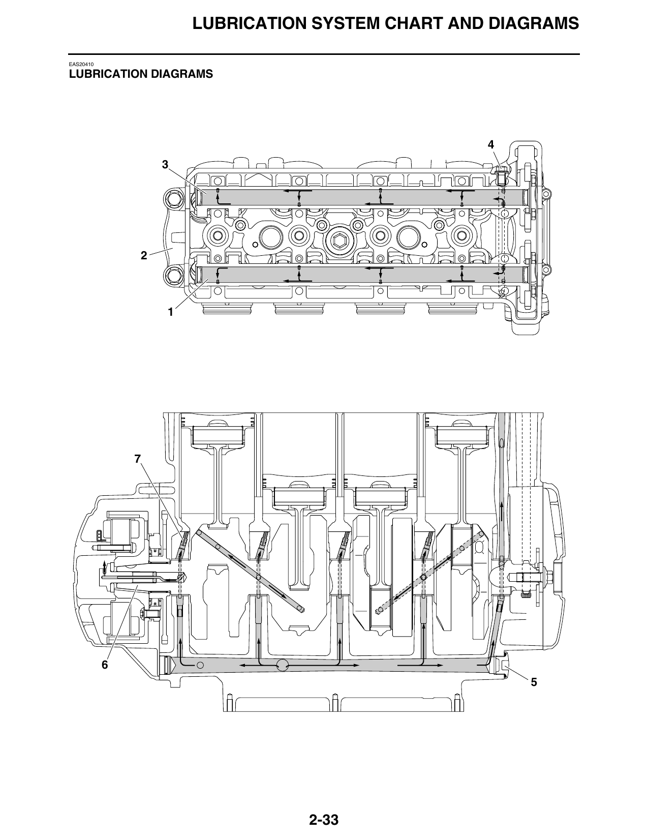
LUBRICATION DIAGRAMS
2-33
LUBRICATION SYSTEM CHART AND DIAGRAMS
1. Intake camshaft
2. Cylinder head
3. Exhaust camshaft
4. Oil check bolt
5. Main gallery bolt
6. Crankshaft
7. Oil nozzle
2-34
LUBRICATION SYSTEM CHART AND DIAGRAMS
2-35
LUBRICATION SYSTEM CHART AND DIAGRAMS
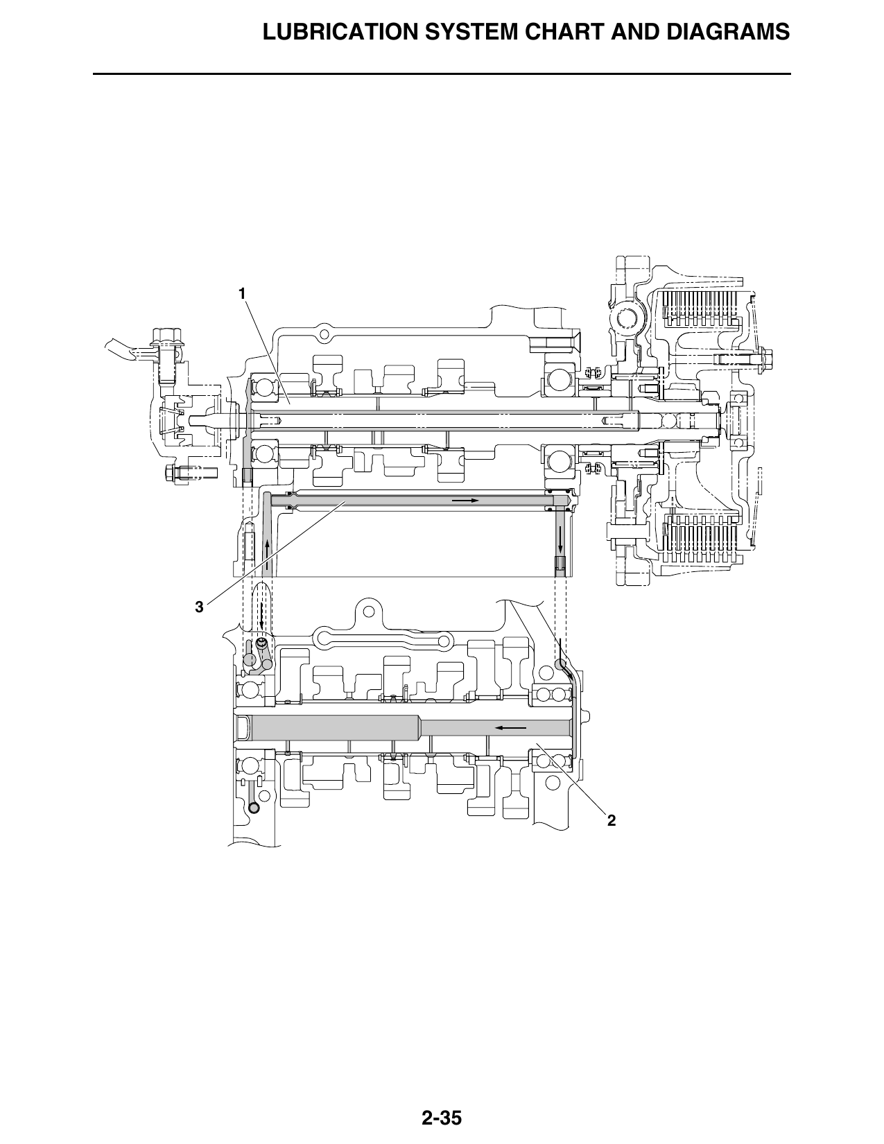
1. Main axle
2. Drive axle
3. Oil delivery pipe 1
2-36
LUBRICATION SYSTEM CHART AND DIAGRAMS
2-37
LUBRICATION SYSTEM CHART AND DIAGRAMS
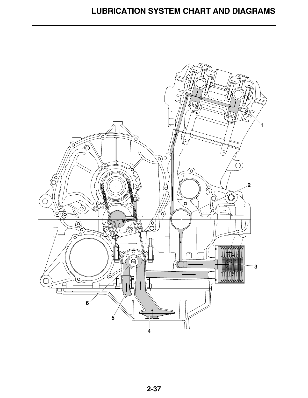
1. Oil check bolt
2. Crankshaft
3. Oil cooler
4. Oil strainer
5. Oil delivery pipe 3
6. Oil pump
2-38
LUBRICATION SYSTEM CHART AND DIAGRAMS
9 8
2-39
LUBRICATION SYSTEM CHART AND DIAGRAMS
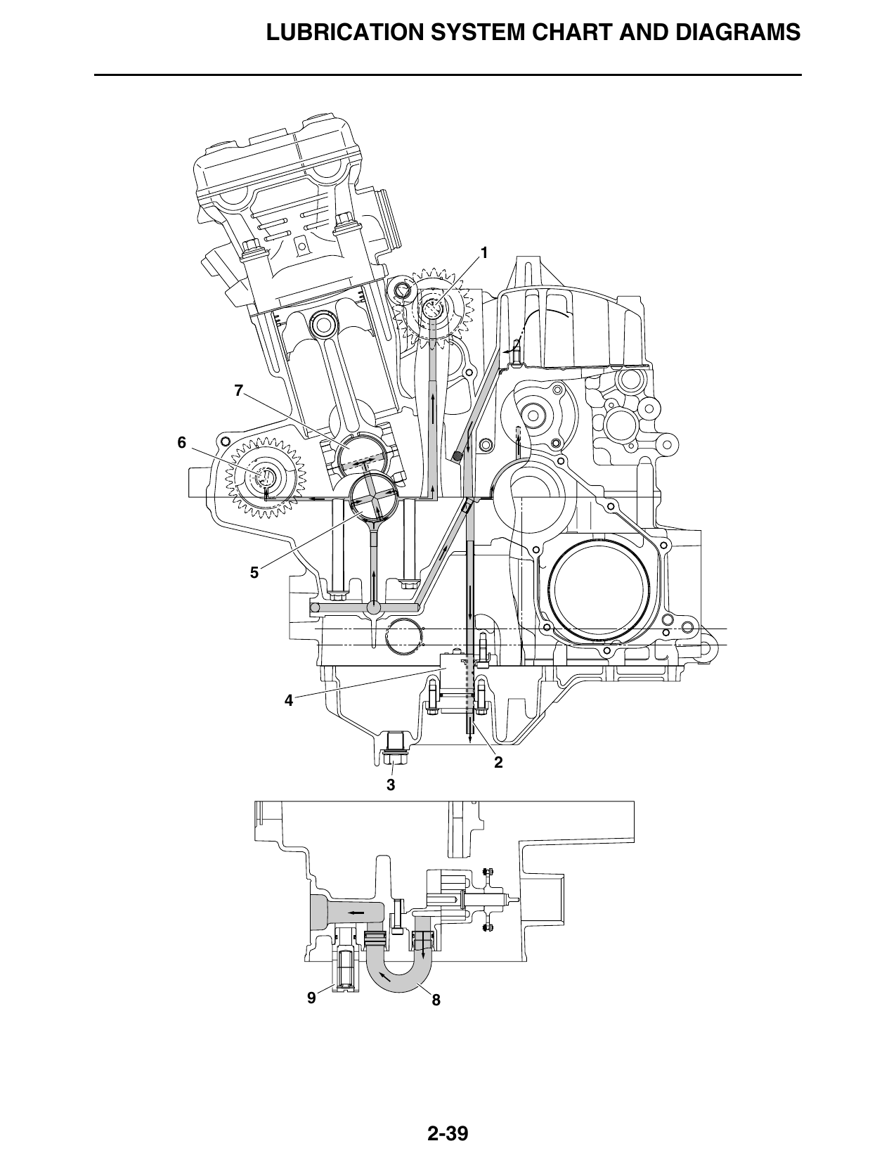
1. Rear balancer
2. Oil delivery pipe 2
3. Engine oil drain bolt
4. Oil level switch
5. Crankshaft
6. Front balancer
7. Crank pin
8. Oil delivery pipe 3
9. Relief valve assembly
2-40
LUBRICATION SYSTEM CHART AND DIAGRAMS
2 4
2-41
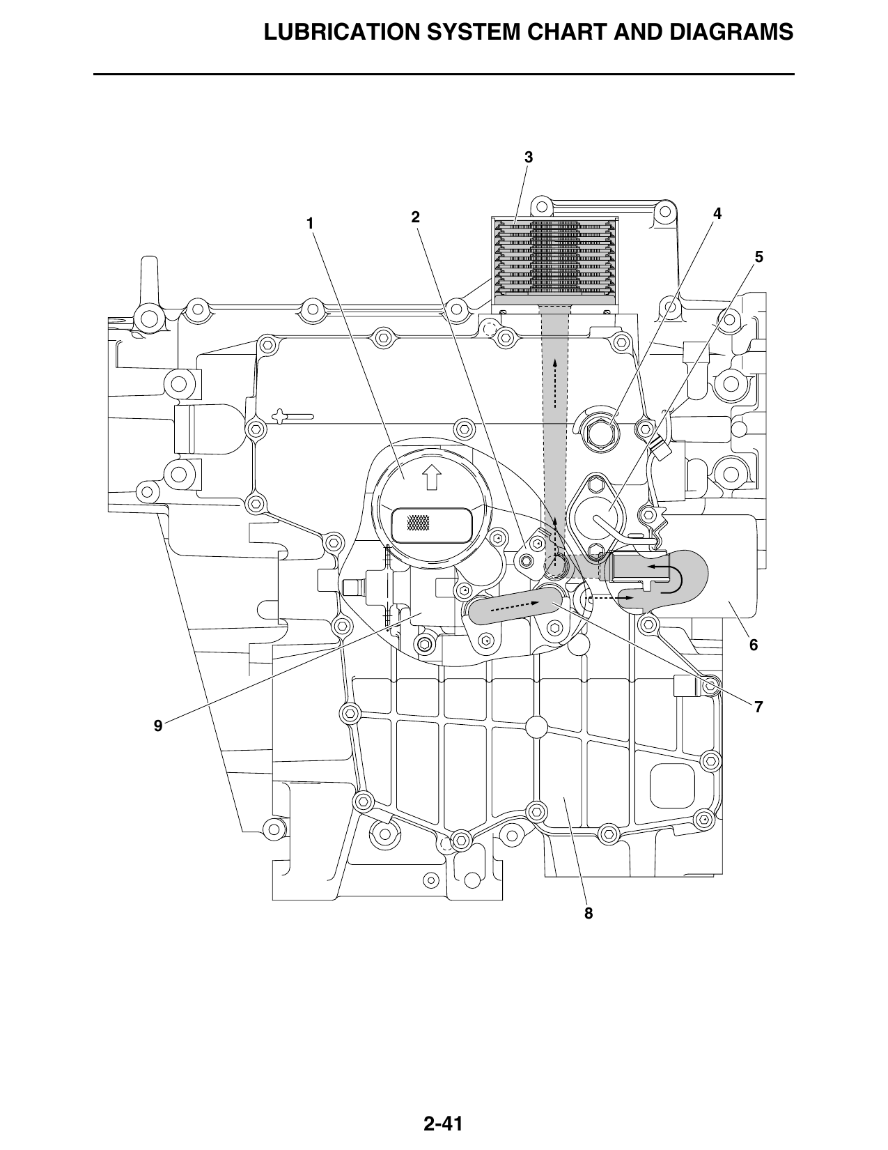
LUBRICATION SYSTEM CHART AND DIAGRAMS
1. Oil strainer
2. Oil delivery pipe 2
3. Oil cooler
4. Engine oil drain bolt
5. Oil level switch
6. Oil filter cartridge
7. Oil delivery pipe 3
8. Oil pan
9. Oil pump
2-42