Bleeding The Hydraulic Clutch System (FJR13AE)
Fragment manuala — str. 158–159
📋 Tekst do skopiowania / wyszukiwania
ENGINE
EWA13010
WARNING
After bleeding the hydraulic clutch system,
check the clutch operation.
▲▲▲▲▲▲▲▲▲▲▲▲▲▲▲▲▲▲▲▲▲▲▲▲▲▲▲▲▲▲▲▲
ET3P66027
BLEEDING THE HYDRAULIC CLUTCH
SYSTEM (FJR13AE)
EWA13000
WARNING
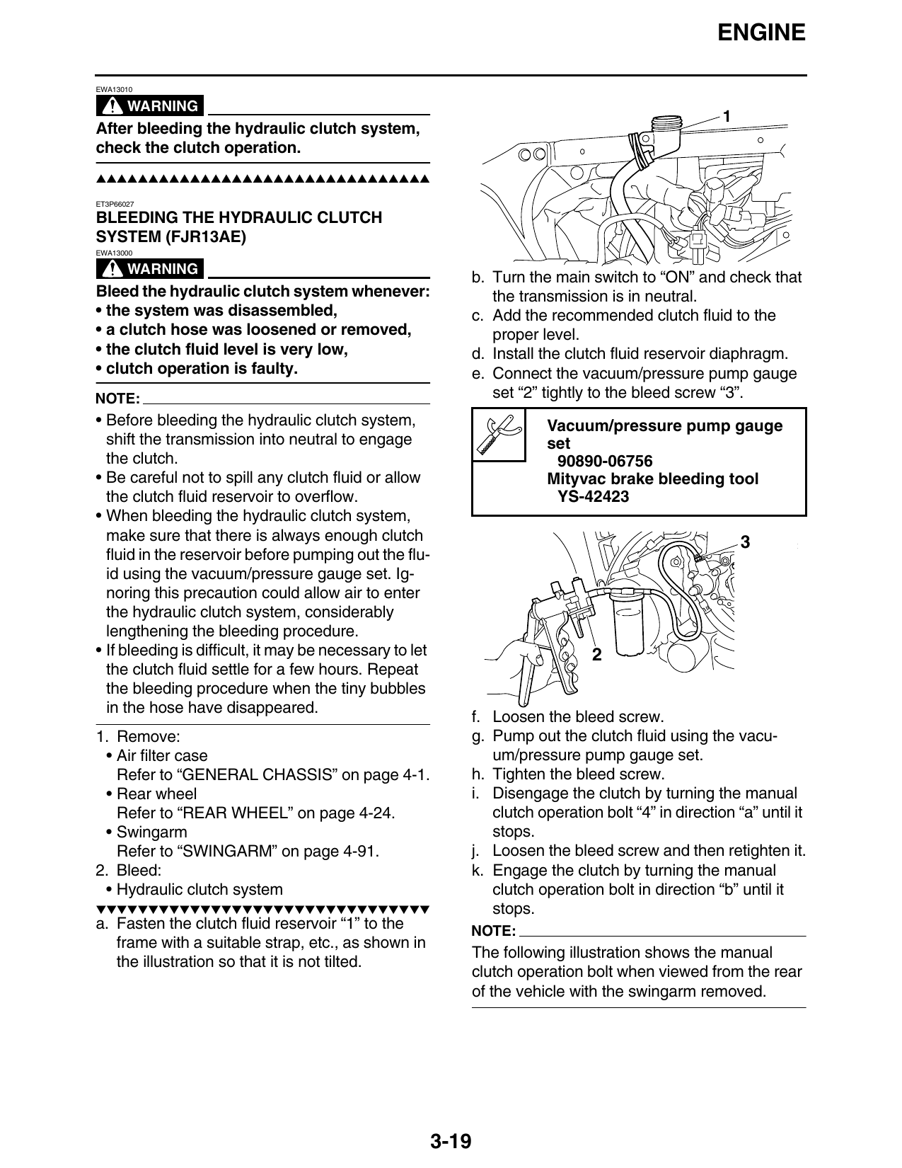
b. Turn the main switch to “ON” and check that
Bleed the hydraulic clutch system whenever: the transmission is in neutral.
• the system was disassembled, c. Add the recommended clutch fluid to the
• a clutch hose was loosened or removed, proper level.
• the clutch fluid level is very low, d. Install the clutch fluid reservoir diaphragm.
• clutch operation is faulty. e. Connect the vacuum/pressure pump gauge
NOTE: set “2” tightly to the bleed screw “3”.
• Before bleeding the hydraulic clutch system, Vacuum/pressure pump gauge
shift the transmission into neutral to engage set
the clutch. 90890-06756
• Be careful not to spill any clutch fluid or allow Mityvac brake bleeding tool
the clutch fluid reservoir to overflow. YS-42423
• When bleeding the hydraulic clutch system,
make sure that there is always enough clutch 3
fluid in the reservoir before pumping out the flu-
id using the vacuum/pressure gauge set. Ig-
noring this precaution could allow air to enter
the hydraulic clutch system, considerably
lengthening the bleeding procedure.
• If bleeding is difficult, it may be necessary to let 2
the clutch fluid settle for a few hours. Repeat
the bleeding procedure when the tiny bubbles
in the hose have disappeared.
f. Loosen the bleed screw.
1. Remove: g. Pump out the clutch fluid using the vacu-
• Air filter case um/pressure pump gauge set.
Refer to “GENERAL CHASSIS” on page 4-1. h. Tighten the bleed screw.
• Rear wheel i. Disengage the clutch by turning the manual
Refer to “REAR WHEEL” on page 4-24. clutch operation bolt “4” in direction “a” until it
• Swingarm stops.
Refer to “SWINGARM” on page 4-91. j. Loosen the bleed screw and then retighten it.
2. Bleed: k. Engage the clutch by turning the manual
• Hydraulic clutch system clutch operation bolt in direction “b” until it
▼▼▼▼▼▼▼▼▼▼▼▼▼▼▼▼▼▼▼▼▼▼▼▼▼▼▼▼▼▼▼▼ stops.
a. Fasten the clutch fluid reservoir “1” to the NOTE:
frame with a suitable strap, etc., as shown in
The following illustration shows the manual
the illustration so that it is not tilted.
clutch operation bolt when viewed from the rear
of the vehicle with the swingarm removed.
3-19
ENGINE
b a
4 3
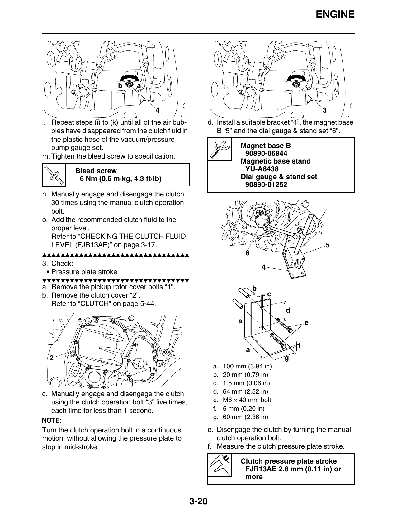
l. Repeat steps (i) to (k) until all of the air bub- d. Install a suitable bracket “4”, the magnet base
bles have disappeared from the clutch fluid in B “5” and the dial gauge & stand set “6”.
the plastic hose of the vacuum/pressure
pump gauge set. Magnet base B
m. Tighten the bleed screw to specification. 90890-06844
Magnetic base stand
Bleed screw YU-A8438
T. 6 Nm (0.6 m·kg, 4.3 ft·lb) Dial gauge & stand set
R.
90890-01252
n. Manually engage and disengage the clutch
30 times using the manual clutch operation
bolt.
o. Add the recommended clutch fluid to the
proper level.
Refer to “CHECKING THE CLUTCH FLUID
LEVEL (FJR13AE)” on page 3-17. 5
▲▲▲▲▲▲▲▲▲▲▲▲▲▲▲▲▲▲▲▲▲▲▲▲▲▲▲▲▲▲▲▲ 6
3. Check:
• Pressure plate stroke
▼▼▼▼▼▼▼▼▼▼▼▼▼▼▼▼▼▼▼▼▼▼▼▼▼▼▼▼▼▼▼▼
a. Remove the pickup rotor cover bolts “1”. b
b. Remove the clutch cover “2”. c
Refer to “CLUTCH” on page 5-44.
d
a e
f
a
2 g
a. 100 mm (3.94 in)
b. 20 mm (0.79 in)
c. 1.5 mm (0.06 in)
c. Manually engage and disengage the clutch d. 64 mm (2.52 in)
using the clutch operation bolt “3” five times, e. M6 × 40 mm bolt
each time for less than 1 second. f. 5 mm (0.20 in)
g. 60 mm (2.36 in)
NOTE:
Turn the clutch operation bolt in a continuous e. Disengage the clutch by turning the manual
motion, without allowing the pressure plate to clutch operation bolt.
stop in mid-stroke. f. Measure the clutch pressure plate stroke.
Clutch pressure plate stroke
FJR13AE 2.8 mm (0.11 in) or
more
3-20