Synchronizing The Throttle Bodies
Fragment manuala — str. 147–148
📋 Tekst do skopiowania / wyszukiwania
ENGINE
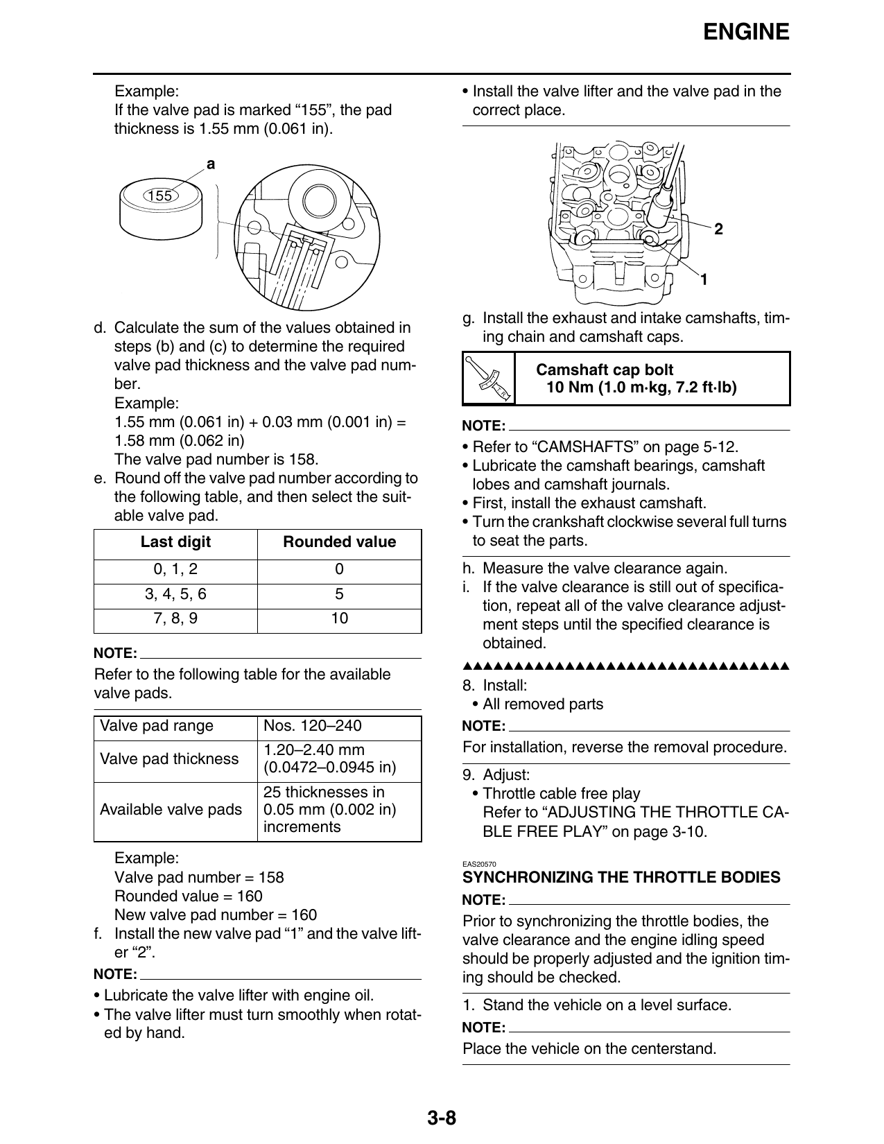
Example: • Install the valve lifter and the valve pad in the
If the valve pad is marked “155”, the pad correct place.
thickness is 1.55 mm (0.061 in).
g. Install the exhaust and intake camshafts, tim-
d. Calculate the sum of the values obtained in
ing chain and camshaft caps.
steps (b) and (c) to determine the required
valve pad thickness and the valve pad num- Camshaft cap bolt
ber. T.
R.
10 Nm (1.0 m·kg, 7.2 ft·lb)
Example:
1.55 mm (0.061 in) + 0.03 mm (0.001 in) = NOTE:
1.58 mm (0.062 in) • Refer to “CAMSHAFTS” on page 5-12.
The valve pad number is 158. • Lubricate the camshaft bearings, camshaft
e. Round off the valve pad number according to lobes and camshaft journals.
the following table, and then select the suit- • First, install the exhaust camshaft.
able valve pad. • Turn the crankshaft clockwise several full turns
Last digit Rounded value to seat the parts.
0, 1, 2 0 h. Measure the valve clearance again.
3, 4, 5, 6 5 i. If the valve clearance is still out of specifica-
tion, repeat all of the valve clearance adjust-
7, 8, 9 10 ment steps until the specified clearance is
obtained.
NOTE:
▲▲▲▲▲▲▲▲▲▲▲▲▲▲▲▲▲▲▲▲▲▲▲▲▲▲▲▲▲▲▲▲
Refer to the following table for the available
8. Install:
valve pads.
• All removed parts
Valve pad range Nos. 120–240 NOTE:
1.20–2.40 mm For installation, reverse the removal procedure.
Valve pad thickness
(0.0472–0.0945 in) 9. Adjust:
25 thicknesses in • Throttle cable free play
Available valve pads 0.05 mm (0.002 in) Refer to “ADJUSTING THE THROTTLE CA-
increments BLE FREE PLAY” on page 3-10.
Example: EAS20570
Valve pad number = 158 SYNCHRONIZING THE THROTTLE BODIES
Rounded value = 160 NOTE:
New valve pad number = 160 Prior to synchronizing the throttle bodies, the
f. Install the new valve pad “1” and the valve lift- valve clearance and the engine idling speed
er “2”. should be properly adjusted and the ignition tim-
NOTE: ing should be checked.
• Lubricate the valve lifter with engine oil.
1. Stand the vehicle on a level surface.
• The valve lifter must turn smoothly when rotat-
ed by hand. NOTE:
Place the vehicle on the centerstand.
3-8
ENGINE
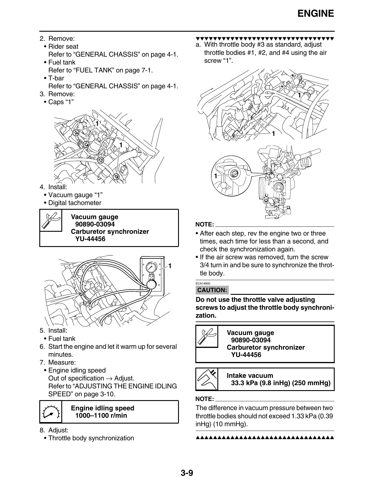
2. Remove: ▼▼▼▼▼▼▼▼▼▼▼▼▼▼▼▼▼▼▼▼▼▼▼▼▼▼▼▼▼▼▼▼
• Rider seat a. With throttle body #3 as standard, adjust
Refer to “GENERAL CHASSIS” on page 4-1. throttle bodies #1, #2, and #4 using the air
• Fuel tank screw “1”.
Refer to “FUEL TANK” on page 7-1.
• T-bar
Refer to “GENERAL CHASSIS” on page 4-1.
3. Remove: 1
• Caps “1”
4. Install:
• Vacuum gauge “1”
• Digital tachometer
Vacuum gauge
90890-03094 NOTE:
Carburetor synchronizer • After each step, rev the engine two or three
YU-44456 times, each time for less than a second, and
check the synchronization again.
• If the air screw was removed, turn the screw
1 3/4 turn in and be sure to synchronize the throt-
tle body.
ECA14900
CAUTION:
Do not use the throttle valve adjusting
screws to adjust the throttle body synchroni-
zation.
5. Install: Vacuum gauge
• Fuel tank 90890-03094
6. Start the engine and let it warm up for several Carburetor synchronizer
minutes. YU-44456
7. Measure:
• Engine idling speed
Out of specification → Adjust. Intake vacuum
Refer to “ADJUSTING THE ENGINE IDLING 33.3 kPa (9.8 inHg) (250 mmHg)
SPEED” on page 3-10.
NOTE:
Engine idling speed The difference in vacuum pressure between two
1000–1100 r/min throttle bodies should not exceed 1.33 kPa (0.39
inHg) (10 mmHg).
8. Adjust:
• Throttle body synchronization ▲▲▲▲▲▲▲▲▲▲▲▲▲▲▲▲▲▲▲▲▲▲▲▲▲▲▲▲▲▲▲▲
3-9