Adjusting The Valve Clearance
Fragment manuala — str. 145–146
📋 Tekst do skopiowania / wyszukiwania
ENGINE
EAS20470
ENGINE Valve clearance (cold)
Intake
EAS20490 0.15–0.22 mm (0.0059–0.0087 in)
ADJUSTING THE VALVE CLEARANCE Exhaust
The following procedure applies to all of the 0.18–0.25 mm (0.0071–0.0098 in)
valves.
NOTE: ▼▼▼▼▼▼▼▼▼▼▼▼▼▼▼▼▼▼▼▼▼▼▼▼▼▼▼▼▼▼▼▼
a. Turn the crankshaft clockwise.
• Valve clearance adjustment should be made
b. When piston #1 is at TDC on the compres-
on a cold engine, at room temperature.
sion stroke, align the TDC mark “a” on the
• When the valve clearance is to be measured or
pickup rotor with the crankcase mating sur-
adjusted, the piston must be at top dead center
face “b”.
(TDC) on the compression stroke.
NOTE:
1. Remove: TDC on the compression stroke can be found
• Rider seat when the camshaft lobes are turned away from
• Right side cowling each other.
Refer to “GENERAL CHASSIS” on page 4-1.
• Fuel tank
Refer to “FUEL TANK” on page 7-1.
• T-bar
Refer to “GENERAL CHASSIS” on page 4-1.
• Air cut-off valve b
Refer to “AIR INDUCTION SYSTEM” on
page 7-11. a
• Thermostat inlet pipe 1
Refer to “THERMOSTAT” on page 6-6.
2. Disconnect:
• Throttle cables
3. Remove: IN EX
• Spark plugs
• Cylinder head cover
• Cylinder head cover gasket
Refer to “CAMSHAFTS” on page 5-12.
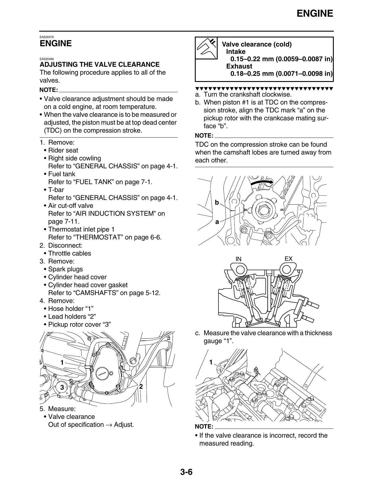
4. Remove:
• Hose holder “1”
• Lead holders “2”
• Pickup rotor cover “3”
c. Measure the valve clearance with a thickness
gauge “1”.
1 1
3 2
5. Measure:
• Valve clearance
Out of specification → Adjust. NOTE:
• If the valve clearance is incorrect, record the
measured reading.
3-6
ENGINE
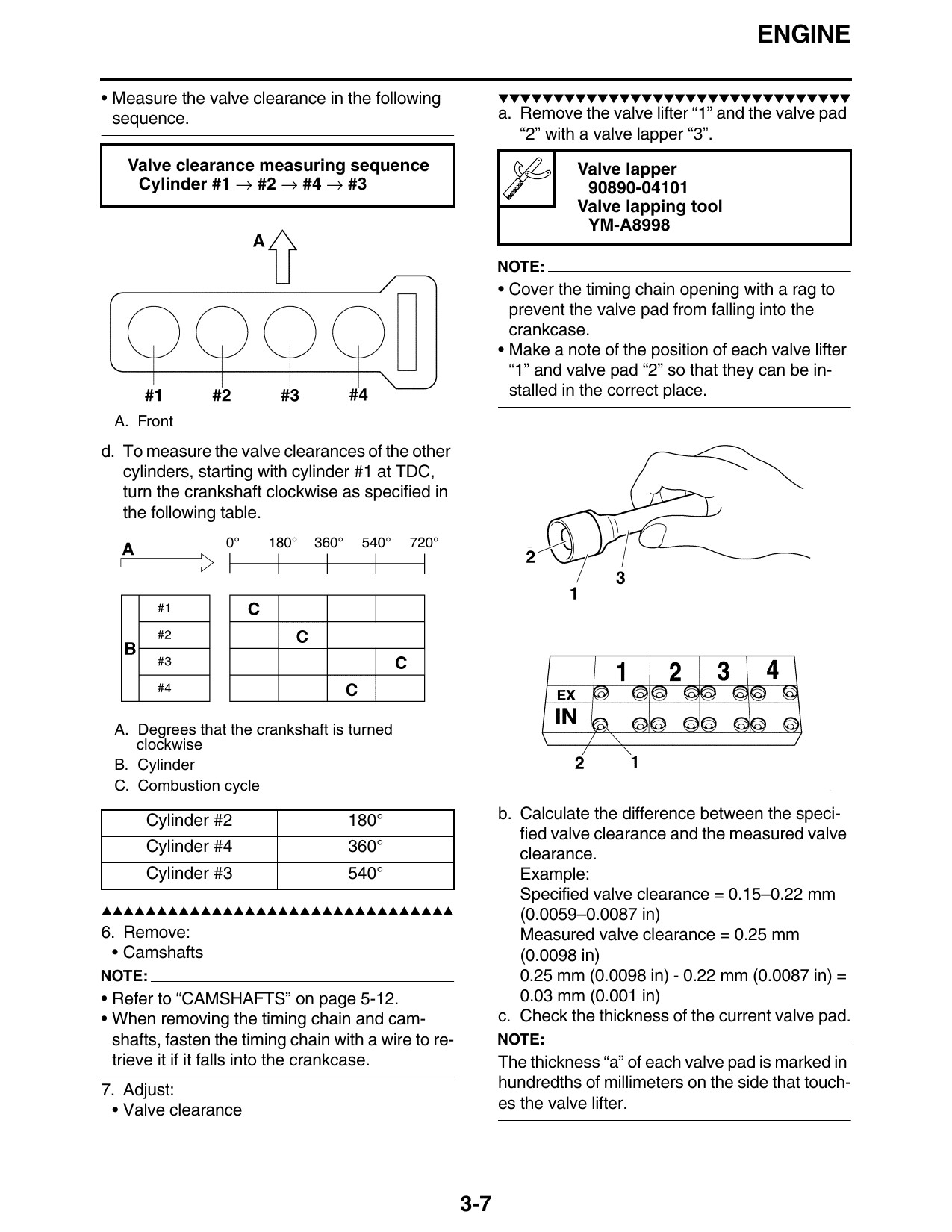
• Measure the valve clearance in the following ▼▼▼▼▼▼▼▼▼▼▼▼▼▼▼▼▼▼▼▼▼▼▼▼▼▼▼▼▼▼▼▼
sequence. a. Remove the valve lifter “1” and the valve pad
“2” with a valve lapper “3”.
Valve clearance measuring sequence Valve lapper
Cylinder #1 → #2 → #4 → #3 90890-04101
Valve lapping tool
YM-A8998
NOTE:
• Cover the timing chain opening with a rag to
prevent the valve pad from falling into the
crankcase.
• Make a note of the position of each valve lifter
“1” and valve pad “2” so that they can be in-
stalled in the correct place.
A. Front
d. To measure the valve clearances of the other
cylinders, starting with cylinder #1 at TDC,
turn the crankshaft clockwise as specified in
the following table.
A. Degrees that the crankshaft is turned
clockwise
B. Cylinder
C. Combustion cycle
Cylinder #2 180° b. Calculate the difference between the speci-
fied valve clearance and the measured valve
Cylinder #4 360° clearance.
Cylinder #3 540° Example:
Specified valve clearance = 0.15–0.22 mm
▲▲▲▲▲▲▲▲▲▲▲▲▲▲▲▲▲▲▲▲▲▲▲▲▲▲▲▲▲▲▲▲ (0.0059–0.0087 in)
6. Remove: Measured valve clearance = 0.25 mm
• Camshafts (0.0098 in)
NOTE: 0.25 mm (0.0098 in) - 0.22 mm (0.0087 in) =
• Refer to “CAMSHAFTS” on page 5-12. 0.03 mm (0.001 in)
• When removing the timing chain and cam- c. Check the thickness of the current valve pad.
shafts, fasten the timing chain with a wire to re- NOTE:
trieve it if it falls into the crankcase. The thickness “a” of each valve pad is marked in
7. Adjust: hundredths of millimeters on the side that touch-
• Valve clearance es the valve lifter.
3-7