Disassembling The Final Drive Assembly
Fragment manuala — str. 290
📋 Tekst do skopiowania / wyszukiwania
SHAFT DRIVE
• Stopper bolt “3” 2. Remove:
• Ring gear “4” • Coupling gear nut
• Coupling gear “1”
Stopper bolt (with the coupling gear/middle shaft tool “2”)
T.
R.
9 Nm (0.9 m·kg, 6.5 ft·lb)
Coupling gear/middle shaft tool
ECA14320
90890-01229
CAUTION:
Gear holder
• The stopper bolt has left-hand threads. To YM-01229
tighten the stopper bolt, turn it counter-
clockwise.
• Apply LOCTITE® onto the stopper bolt.
3. Remove:
• Bearing retainer
(with the bearing retainer wrench “1”)
4. Measure:
• Ring-gear-to-stopper-bolt clearance Bearing retainer wrench
90890-04050
Ring-gear-to-stopper-bolt clear- Pinion bearing retainer & remov-
ance er
0.30–0.60 mm (0.0118–0.0236 in) YM-04050
ECA14330
NOTE:
CAUTION:
If the ring-gear-to-stopper-bolt clearance is out
of specification, repeat the above procedure. The bearing retainer has left-hand threads.
To loosen the bearing retainer, turn it clock-
EAS23620
wise.
DISASSEMBLING THE FINAL DRIVE
ASSEMBLY
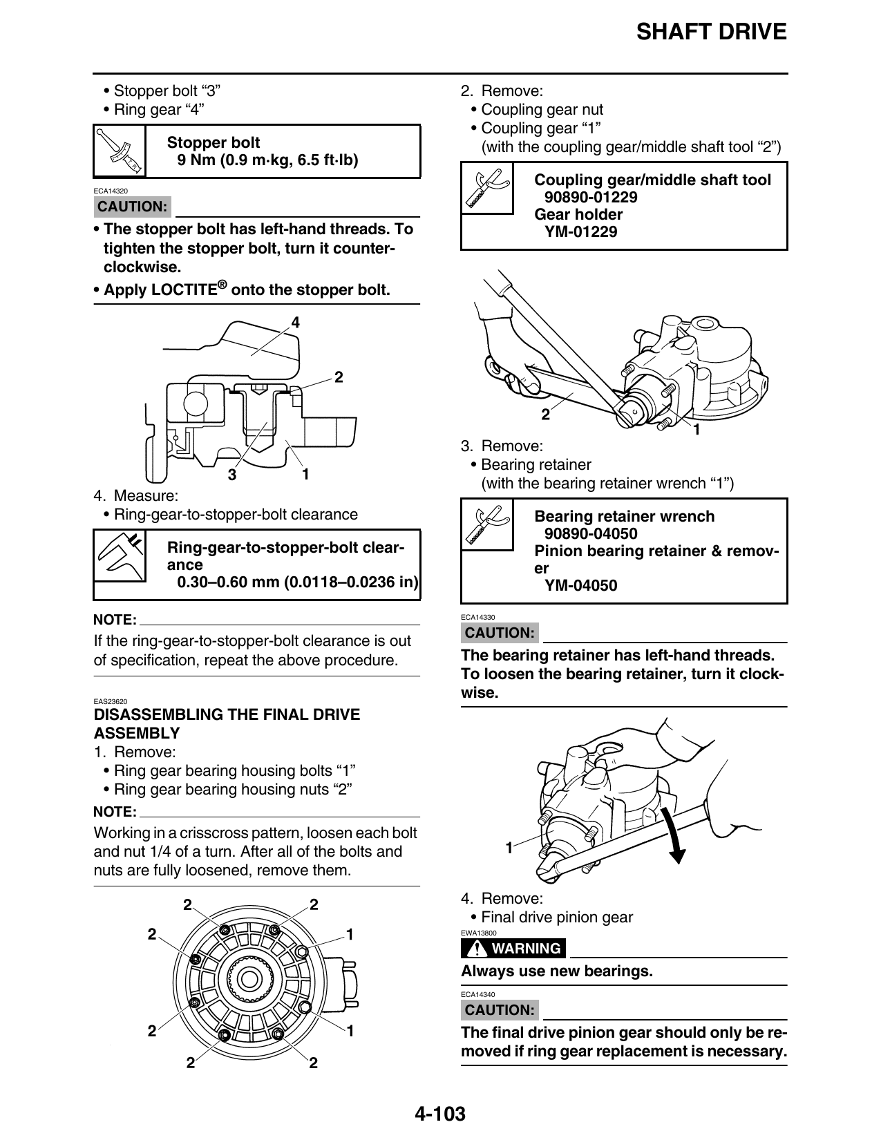
1. Remove:
• Ring gear bearing housing bolts “1”
• Ring gear bearing housing nuts “2”
NOTE:
Working in a crisscross pattern, loosen each bolt
and nut 1/4 of a turn. After all of the bolts and
nuts are fully loosened, remove them.
4. Remove:
• Final drive pinion gear
EWA13800
WARNING
Always use new bearings.
ECA14340
CAUTION:
The final drive pinion gear should only be re-
moved if ring gear replacement is necessary.
4-103