🏍️ FJR1300 RP13

Removing And Installing The Bearings

Fragment manuala — str. 291–293

📋 Tekst do skopiowania / wyszukiwania
SHAFT DRIVE

NOTE:                                                  ▼▼▼▼▼▼▼▼▼▼▼▼▼▼▼▼▼▼▼▼▼▼▼▼▼▼▼▼▼▼▼▼
                                                       a. Heat the final gear case to approximately 150
Lightly tap on the end of the final drive pinion
                                                          °C (302 °F).
gear with a soft hammer.
                                                       b. Install the bearing outer races with a socket
                                                          or appropriate tool that matches the diameter
EAS23630
                                                          of the races.
REMOVING AND INSTALLING THE
                                                       c. Install the inner race onto the final drive pin-
BEARINGS
                                                          ion gear.
1. Check:
                                                       ▲▲▲▲▲▲▲▲▲▲▲▲▲▲▲▲▲▲▲▲▲▲▲▲▲▲▲▲▲▲▲▲
 • Bearings
   Damage → Replace.                                   5. Install:
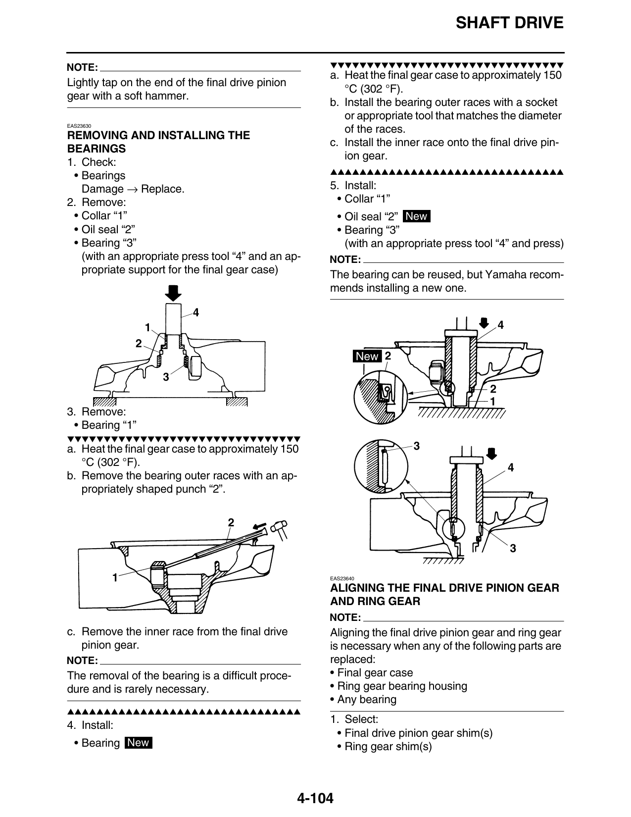
2. Remove:                                              • Collar “1”
 • Collar “1”                                              • Oil seal “2” New
 • Oil seal “2”                                            • Bearing “3”
 • Bearing “3”                                               (with an appropriate press tool “4” and press)
   (with an appropriate press tool “4” and an ap-      NOTE:
   propriate support for the final gear case)          The bearing can be reused, but Yamaha recom-
                                                       mends installing a new one.

3. Remove:
 • Bearing “1”
▼▼▼▼▼▼▼▼▼▼▼▼▼▼▼▼▼▼▼▼▼▼▼▼▼▼▼▼▼▼▼▼
a. Heat the final gear case to approximately 150
   °C (302 °F).
b. Remove the bearing outer races with an ap-
   propriately shaped punch “2”.

                                                       EAS23640

                                                       ALIGNING THE FINAL DRIVE PINION GEAR
                                                       AND RING GEAR
                                                       NOTE:
c. Remove the inner race from the final drive          Aligning the final drive pinion gear and ring gear
   pinion gear.                                        is necessary when any of the following parts are
NOTE:                                                  replaced:
The removal of the bearing is a difficult proce-       • Final gear case
dure and is rarely necessary.                          • Ring gear bearing housing
                                                       • Any bearing
▲▲▲▲▲▲▲▲▲▲▲▲▲▲▲▲▲▲▲▲▲▲▲▲▲▲▲▲▲▲▲▲
                                                       1. Select:
4. Install:
                                                        • Final drive pinion gear shim(s)
  • Bearing New                                         • Ring gear shim(s)

                                                   4-104
                                                                                   SHAFT DRIVE

▼▼▼▼▼▼▼▼▼▼▼▼▼▼▼▼▼▼▼▼▼▼▼▼▼▼▼▼▼▼▼▼                            Therefore, the calculated final drive pinion
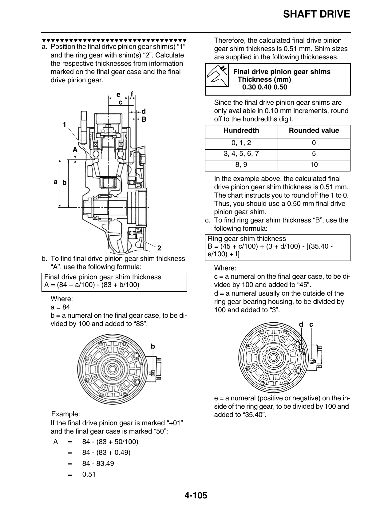
a. Position the final drive pinion gear shim(s) “1”         gear shim thickness is 0.51 mm. Shim sizes
   and the ring gear with shim(s) “2”. Calculate            are supplied in the following thicknesses.
   the respective thicknesses from information
   marked on the final gear case and the final                    Final drive pinion gear shims
   drive pinion gear.                                              Thickness (mm)
                                                                     0.30 0.40 0.50
                                e     f
                                 c                          Since the final drive pinion gear shims are
                                          d                 only available in 0.10 mm increments, round
                                          B                 off to the hundredths digit.
                                                               Hundredth             Rounded value
                                                                  0, 1, 2                    0
               A
                                                               3, 4, 5, 6, 7                 5
                                                                   8, 9                      10

    a b                                                    In the example above, the calculated final
                                                           drive pinion gear shim thickness is 0.51 mm.
                                                           The chart instructs you to round off the 1 to 0.
                                                           Thus, you should use a 0.50 mm final drive
                                                           pinion gear shim.
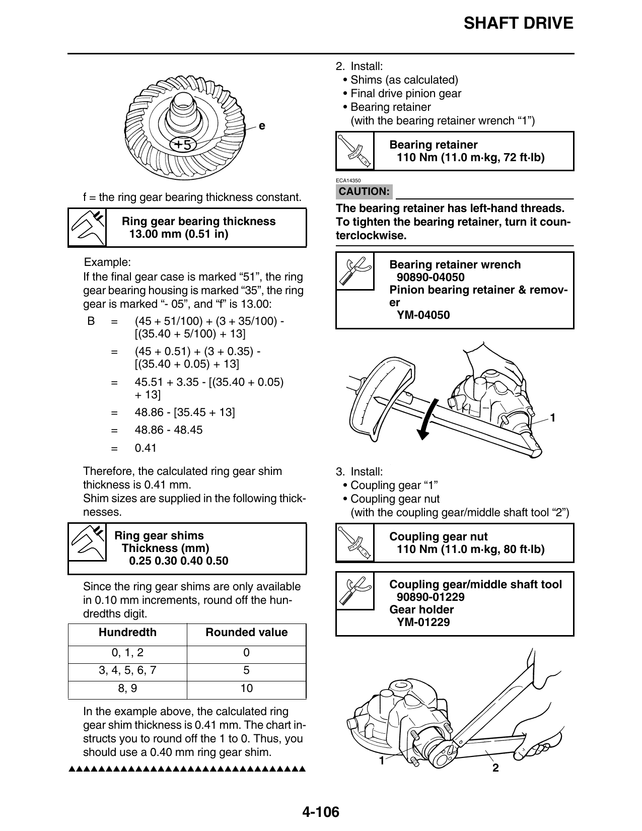
                                                        c. To find ring gear shim thickness “B”, use the
                                                           following formula:
                                                         Ring gear shim thickness
                                         2               B = (45 + c/100) + (3 + d/100) - [(35.40 -
                                                         e/100) + f]
b. To find final drive pinion gear shim thickness
   “A”, use the following formula:                          Where:
 Final drive pinion gear shim thickness                     c = a numeral on the final gear case, to be di-
 A = (84 + a/100) - (83 + b/100)                            vided by 100 and added to “45”.
                                                            d = a numeral usually on the outside of the
   Where:                                                   ring gear bearing housing, to be divided by
   a = 84                                                   100 and added to “3”.
   b = a numeral on the final gear case, to be di-
   vided by 100 and added to “83”.

                                                            e = a numeral (positive or negative) on the in-
                                                            side of the ring gear, to be divided by 100 and
   Example:                                                 added to “35.40”.
   If the final drive pinion gear is marked “+01”
   and the final gear case is marked “50”:
    A = 84 - (83 + 50/100)
           =       84 - (83 + 0.49)
           =       84 - 83.49
           =       0.51

                                                    4-105
                                                                                  SHAFT DRIVE

                                                     2. Install:
                                                      • Shims (as calculated)
                                                      • Final drive pinion gear
                                                      • Bearing retainer
                                                        (with the bearing retainer wrench “1”)

                                                                     Bearing retainer
                                                            T.
                                                                R.
                                                                      110 Nm (11.0 m·kg, 72 ft·lb)
                                                     ECA14350

                                                     CAUTION:
 f = the ring gear bearing thickness constant.
                                                     The bearing retainer has left-hand threads.
          Ring gear bearing thickness                To tighten the bearing retainer, turn it coun-
           13.00 mm (0.51 in)                        terclockwise.

 Example:                                                            Bearing retainer wrench
 If the final gear case is marked “51”, the ring                      90890-04050
 gear bearing housing is marked “35”, the ring                       Pinion bearing retainer & remov-
 gear is marked “- 05”, and “f” is 13.00:                            er
  B = (45 + 51/100) + (3 + 35/100) -                                  YM-04050
              [(35.40 + 5/100) + 13]
      =      (45 + 0.51) + (3 + 0.35) -
             [(35.40 + 0.05) + 13]
      =      45.51 + 3.35 - [(35.40 + 0.05)
             + 13]
      =      48.86 - [35.45 + 13]
      =      48.86 - 48.45
      =      0.41

 Therefore, the calculated ring gear shim            3. Install:
 thickness is 0.41 mm.                                • Coupling gear “1”
 Shim sizes are supplied in the following thick-      • Coupling gear nut
 nesses.                                                (with the coupling gear/middle shaft tool “2”)

       Ring gear shims                                               Coupling gear nut
        Thickness (mm)                                      T.
                                                                R.
                                                                      110 Nm (11.0 m·kg, 80 ft·lb)
         0.25 0.30 0.40 0.50

 Since the ring gear shims are only available                        Coupling gear/middle shaft tool
 in 0.10 mm increments, round off the hun-                            90890-01229
 dredths digit.                                                      Gear holder
                                                                      YM-01229
    Hundredth                Rounded value
       0, 1, 2                      0
    3, 4, 5, 6, 7                   5
          8, 9                      10

 In the example above, the calculated ring
 gear shim thickness is 0.41 mm. The chart in-
 structs you to round off the 1 to 0. Thus, you
 should use a 0.40 mm ring gear shim.
▲▲▲▲▲▲▲▲▲▲▲▲▲▲▲▲▲▲▲▲▲▲▲▲▲▲▲▲▲▲▲▲

                                                 4-106