Hydraulic Unit Operation Tests
Fragment manuala — str. 247–249
📋 Tekst do skopiowania / wyszukiwania
ABS (ANTI-LOCK BRAKE SYSTEM)
5. Fill: The hydraulic unit operation can be tested using
• Brake master cylinder reservoir the following two methods.
• Brake fluid reservoir • Hydraulic unit operation test 1: this test checks
(with the specified amount of the recom- the function of the ABS after the system was
mended brake fluid) disassembled, adjusted, or serviced.
• Hydraulic unit operation test 2: this test gener-
Recommended fluid ates the same reaction-force pulsating action
DOT 4 that is generated in the brake lever and brake
EWA13090
pedal when the ABS is activated.
WARNING
Hydraulic unit operation test 1
• Use only the designated brake fluid. Other EWA13120
brake fluids may cause the rubber seals to WARNING
deteriorate, causing leakage and poor Securely support the vehicle so that there is
brake performance. no danger of it falling over.
• Refill with the same type of brake fluid that
is already in the system. Mixing brake fluids NOTE:
may result in a harmful chemical reaction, Two people are necessary to perform hydraulic
leading to poor brake performance. unit operation test 1.
• When refilling, be careful that water does
not enter the brake fluid reservoir. Water 1. Place the vehicle on the centerstand.
will significantly lower the boiling point of 2. Turn the main switch to “OFF”.
the brake fluid and could cause vapor lock. 3. Remove:
• Front cowling right inner panel 1
ECA13540
Refer to “GENERAL CHASSIS” on page 4-1.
CAUTION:
4. Check:
Brake fluid may damage painted surfaces • Battery voltage
and plastic parts. Therefore, always clean up Lower than 12.8 V → Charge or replace the
any spilt brake fluid immediately. battery.
6. Bleed:
• Brake system Battery voltage
Refer to “BLEEDING THE HYDRAULIC Higher than 12.8 V
BRAKE SYSTEM (ABS)” on page 3-31.
NOTE:
7. Check the operation of the hydraulic unit ac-
cording to the brake lever and the brake ped- • If the battery voltage is lower than 12.8 V,
al response. (Refer to “HYDRAULIC UNIT charge the battery, and then perform hydraulic
OPERATION TESTS” on page 4-60.) unit operation test 1.
ECA14770 • If the battery voltage is lower than 10 V, the
CAUTION: ABS warning light comes on and the ABS does
Always check the operation of the hydraulic not operate.
unit according to the brake lever and the
brake pedal response.
8. Delete the malfunction codes. (Refer to “[D-1]
DELETING THE MALFUNCTION CODES”
on page 8-155.)
9. Perform a trial run. (Refer to “TRIAL RUN” on
page 4-63.)
EAS22800
HYDRAULIC UNIT OPERATION TESTS
The reaction-force pulsating action generated in
the brake lever and brake pedal when the ABS
is activated can be tested when the vehicle is
stopped.
4-60
ABS (ANTI-LOCK BRAKE SYSTEM)
5. Connect the test coupler adapter “1” to the force is released during the second pulse in the
ABS test coupler “2”. brake pedal, the second person will be able to
rotate the rear wheel for 0.1 second.
Test coupler adapter
90890-03149
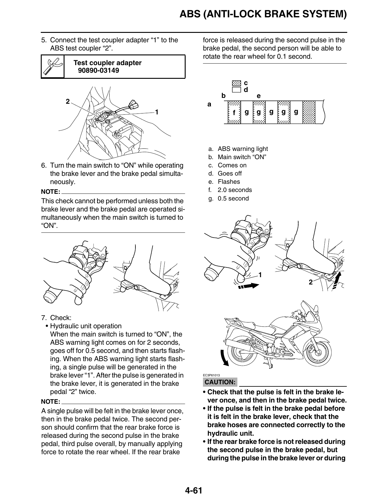
a. ABS warning light
b. Main switch “ON”
6. Turn the main switch to “ON” while operating c. Comes on
the brake lever and the brake pedal simulta- d. Goes off
neously. e. Flashes
NOTE: f. 2.0 seconds
This check cannot be performed unless both the g. 0.5 second
brake lever and the brake pedal are operated si-
multaneously when the main switch is turned to
“ON”.
7. Check:
• Hydraulic unit operation
When the main switch is turned to “ON”, the
ABS warning light comes on for 2 seconds,
goes off for 0.5 second, and then starts flash-
ing. When the ABS warning light starts flash-
ing, a single pulse will be generated in the
brake lever “1”. After the pulse is generated in EC3P61013
the brake lever, it is generated in the brake CAUTION:
pedal “2” twice. • Check that the pulse is felt in the brake le-
NOTE: ver once, and then in the brake pedal twice.
A single pulse will be felt in the brake lever once, • If the pulse is felt in the brake pedal before
then in the brake pedal twice. The second per- it is felt in the brake lever, check that the
son should confirm that the rear brake force is brake hoses are connected correctly to the
released during the second pulse in the brake hydraulic unit.
pedal, third pulse overall, by manually applying • If the rear brake force is not released during
force to rotate the rear wheel. If the rear brake the second pulse in the brake pedal, but
during the pulse in the brake lever or during
4-61
ABS (ANTI-LOCK BRAKE SYSTEM)
the first pulse in the brake pedal, check that
the brake hoses are connected correctly to
the hydraulic unit. 2
• If the pulse is hardly felt in either the brake 1
lever or brake pedal, check that the brake
hoses are connected correctly to the hy-
draulic unit.
• If the operation of the hydraulic unit is normal,
delete all of the malfunction codes.
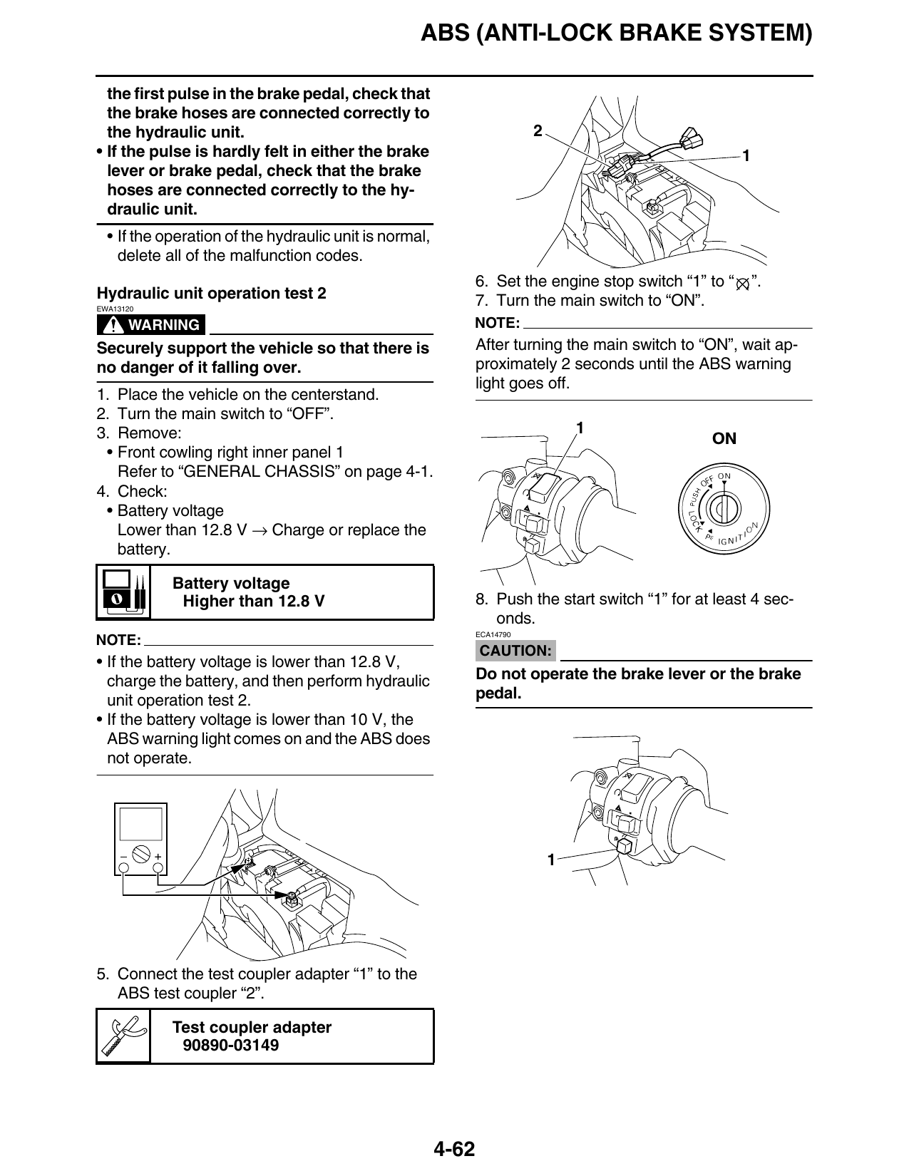
6. Set the engine stop switch “1” to “ ”.
Hydraulic unit operation test 2 7. Turn the main switch to “ON”.
EWA13120
WARNING NOTE:
Securely support the vehicle so that there is After turning the main switch to “ON”, wait ap-
no danger of it falling over. proximately 2 seconds until the ABS warning
light goes off.
1. Place the vehicle on the centerstand.
2. Turn the main switch to “OFF”.
3. Remove: 1
• Front cowling right inner panel 1
Refer to “GENERAL CHASSIS” on page 4-1.
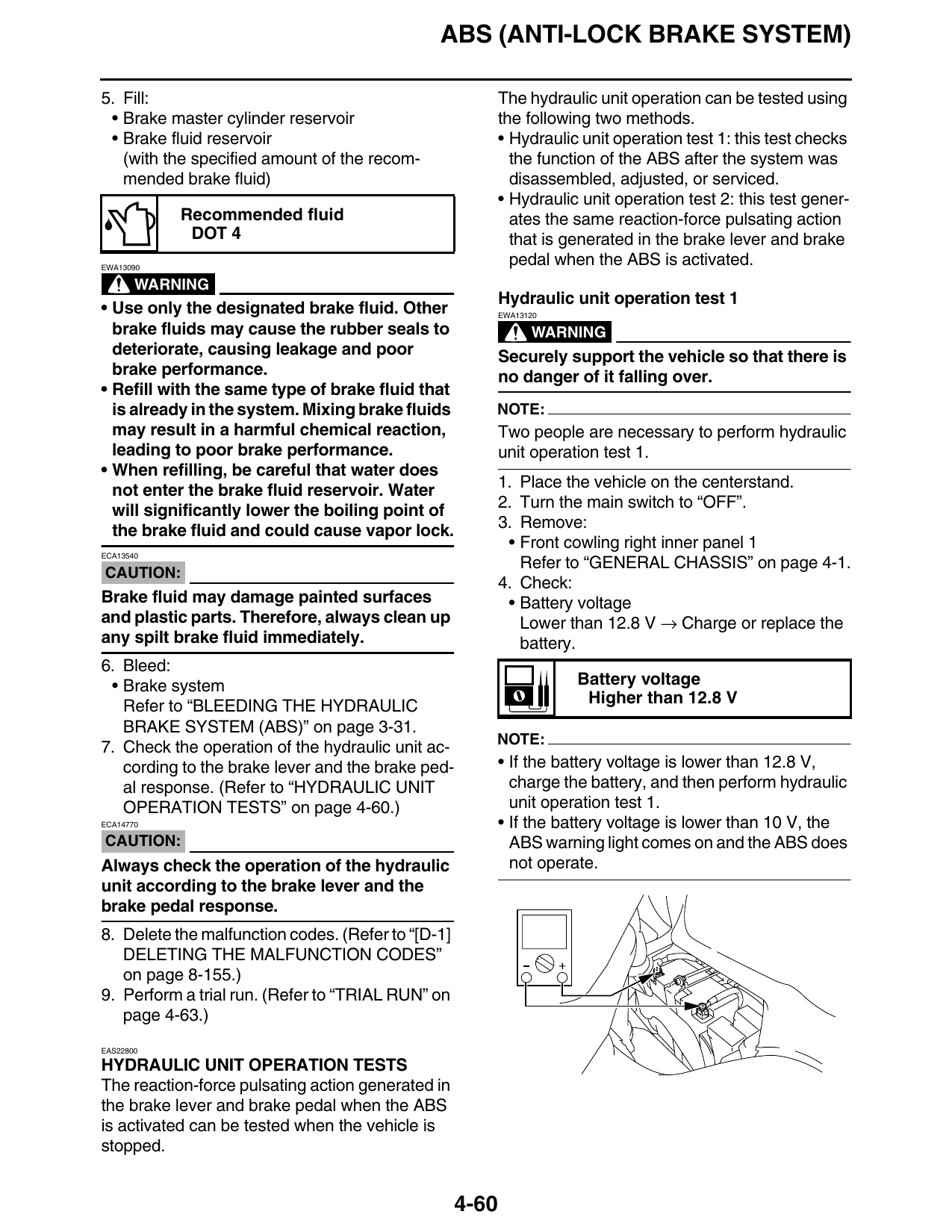
4. Check:
• Battery voltage
Lower than 12.8 V → Charge or replace the
battery.
Battery voltage
Higher than 12.8 V 8. Push the start switch “1” for at least 4 sec-
onds.
ECA14790
NOTE:
CAUTION:
• If the battery voltage is lower than 12.8 V,
charge the battery, and then perform hydraulic Do not operate the brake lever or the brake
unit operation test 2. pedal.
• If the battery voltage is lower than 10 V, the
ABS warning light comes on and the ABS does
not operate.
5. Connect the test coupler adapter “1” to the
ABS test coupler “2”.
Test coupler adapter
90890-03149
4-62