Installing The Handlebars (FJR13AE)
Fragment manuala — str. 257–259
📋 Tekst do skopiowania / wyszukiwania
HANDLEBARS
EWA13700
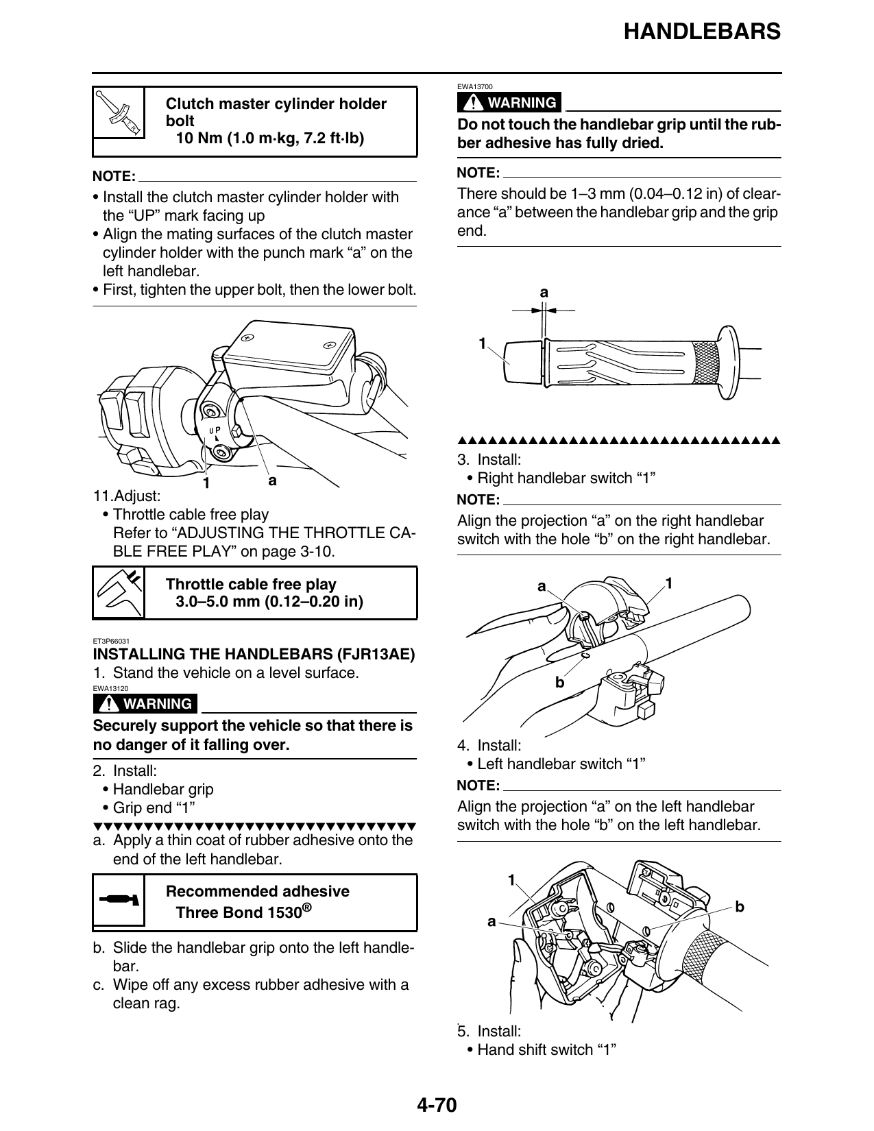
Clutch master cylinder holder WARNING
T.
R.
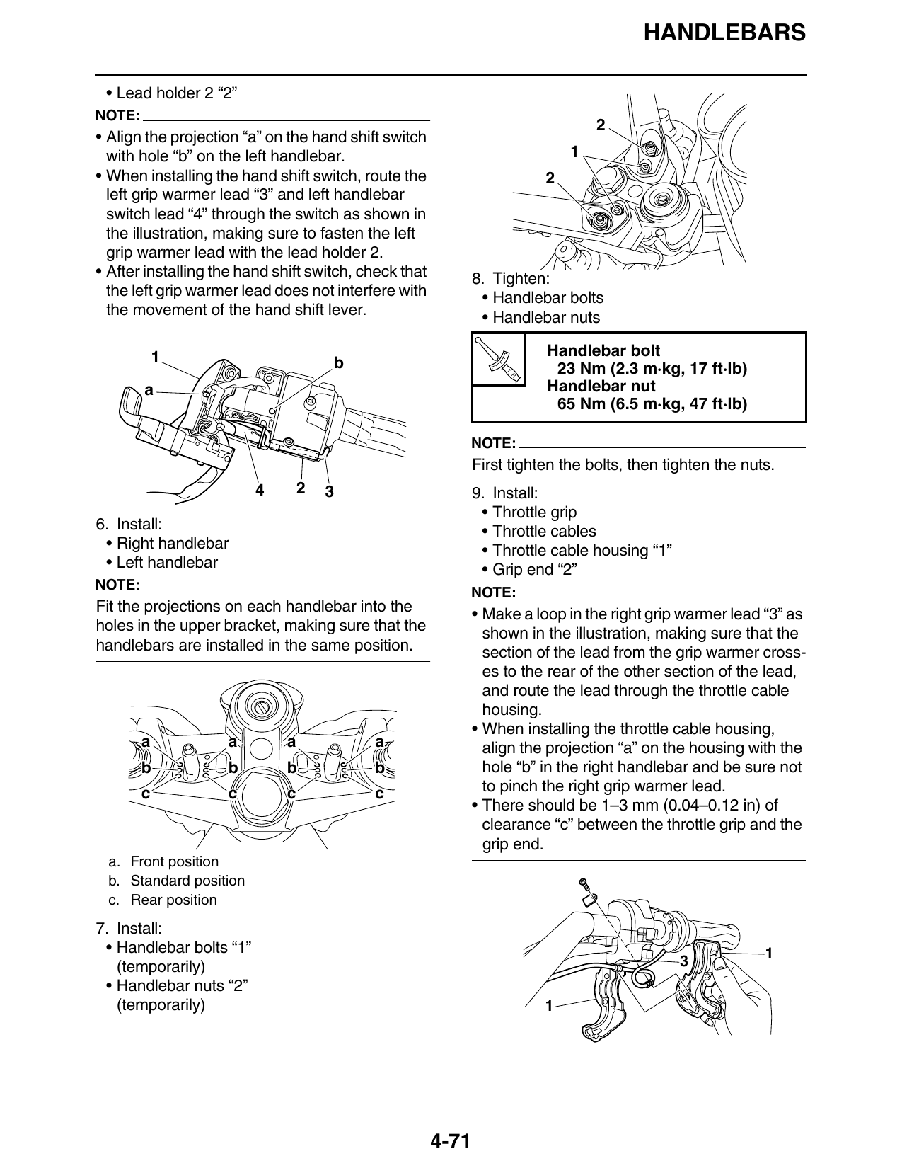
bolt Do not touch the handlebar grip until the rub-
10 Nm (1.0 m·kg, 7.2 ft·lb) ber adhesive has fully dried.
NOTE: NOTE:
• Install the clutch master cylinder holder with There should be 1–3 mm (0.04–0.12 in) of clear-
the “UP” mark facing up ance “a” between the handlebar grip and the grip
• Align the mating surfaces of the clutch master end.
cylinder holder with the punch mark “a” on the
left handlebar.
• First, tighten the upper bolt, then the lower bolt.
▲▲▲▲▲▲▲▲▲▲▲▲▲▲▲▲▲▲▲▲▲▲▲▲▲▲▲▲▲▲▲▲
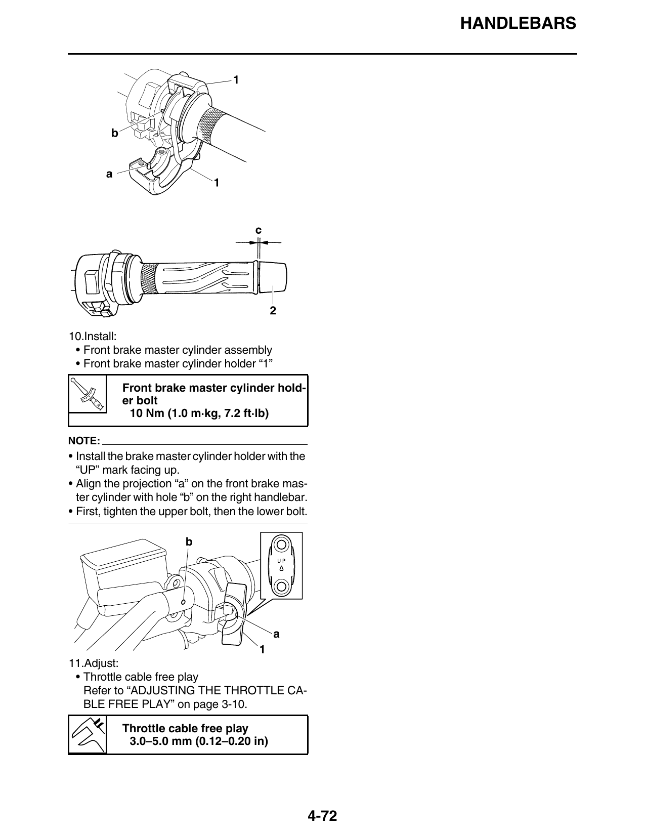
3. Install:
• Right handlebar switch “1”
11.Adjust: NOTE:
• Throttle cable free play Align the projection “a” on the right handlebar
Refer to “ADJUSTING THE THROTTLE CA- switch with the hole “b” on the right handlebar.
BLE FREE PLAY” on page 3-10.
Throttle cable free play
3.0–5.0 mm (0.12–0.20 in)
ET3P66031
INSTALLING THE HANDLEBARS (FJR13AE)
1. Stand the vehicle on a level surface.
EWA13120
WARNING
Securely support the vehicle so that there is
no danger of it falling over. 4. Install:
2. Install: • Left handlebar switch “1”
• Handlebar grip NOTE:
• Grip end “1” Align the projection “a” on the left handlebar
▼▼▼▼▼▼▼▼▼▼▼▼▼▼▼▼▼▼▼▼▼▼▼▼▼▼▼▼▼▼▼▼ switch with the hole “b” on the left handlebar.
a. Apply a thin coat of rubber adhesive onto the
end of the left handlebar.
Recommended adhesive
Three Bond 1530®
b. Slide the handlebar grip onto the left handle-
bar.
c. Wipe off any excess rubber adhesive with a
clean rag.
5. Install:
• Hand shift switch “1”
4-70
HANDLEBARS
• Lead holder 2 “2”
NOTE:
• Align the projection “a” on the hand shift switch
with hole “b” on the left handlebar. 1
• When installing the hand shift switch, route the 2
left grip warmer lead “3” and left handlebar
switch lead “4” through the switch as shown in
the illustration, making sure to fasten the left
grip warmer lead with the lead holder 2.
• After installing the hand shift switch, check that 8. Tighten:
the left grip warmer lead does not interfere with • Handlebar bolts
the movement of the hand shift lever. • Handlebar nuts
1 Handlebar bolt
b T. 23 Nm (2.3 m·kg, 17 ft·lb)
R.
a Handlebar nut
65 Nm (6.5 m·kg, 47 ft·lb)
NOTE:
First tighten the bolts, then tighten the nuts.
4 2 3 9. Install:
• Throttle grip
6. Install: • Throttle cables
• Right handlebar • Throttle cable housing “1”
• Left handlebar • Grip end “2”
NOTE:
NOTE:
Fit the projections on each handlebar into the • Make a loop in the right grip warmer lead “3” as
holes in the upper bracket, making sure that the shown in the illustration, making sure that the
handlebars are installed in the same position. section of the lead from the grip warmer cross-
es to the rear of the other section of the lead,
and route the lead through the throttle cable
housing.
• When installing the throttle cable housing,
a a a a align the projection “a” on the housing with the
b b b b hole “b” in the right handlebar and be sure not
c c c c to pinch the right grip warmer lead.
• There should be 1–3 mm (0.04–0.12 in) of
clearance “c” between the throttle grip and the
grip end.
a. Front position
b. Standard position
c. Rear position
7. Install:
• Handlebar bolts “1” 1
(temporarily) 3
• Handlebar nuts “2”
(temporarily) 1
4-71
HANDLEBARS
10.Install:
• Front brake master cylinder assembly
• Front brake master cylinder holder “1”
Front brake master cylinder hold-
T.
R.
er bolt
10 Nm (1.0 m·kg, 7.2 ft·lb)
NOTE:
• Install the brake master cylinder holder with the
“UP” mark facing up.
• Align the projection “a” on the front brake mas-
ter cylinder with hole “b” on the right handlebar.
• First, tighten the upper bolt, then the lower bolt.
b
a
11.Adjust:
• Throttle cable free play
Refer to “ADJUSTING THE THROTTLE CA-
BLE FREE PLAY” on page 3-10.
Throttle cable free play
3.0–5.0 mm (0.12–0.20 in)
4-72