Removing The Handlebars
Fragment manuala — str. 255–256
📋 Tekst do skopiowania / wyszukiwania
HANDLEBARS
EAS22870 EWA13700
REMOVING THE HANDLEBARS WARNING
1. Stand the vehicle on a level surface. Do not touch the handlebar grip until the rub-
EWA13120
WARNING ber adhesive has fully dried.
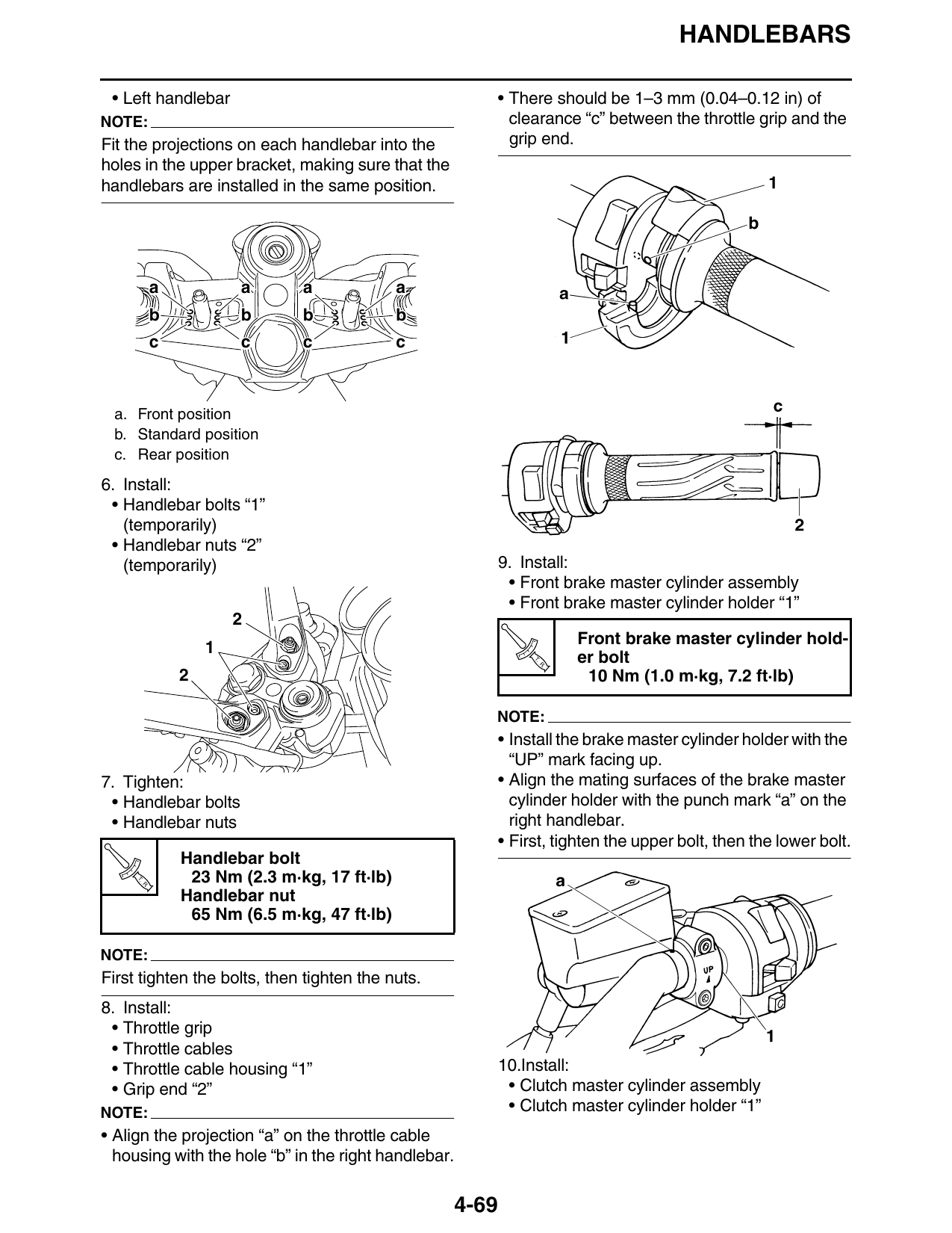
Securely support the vehicle so that there is NOTE:
no danger of it falling over. There should be 1–3 mm (0.04–0.12 in) of clear-
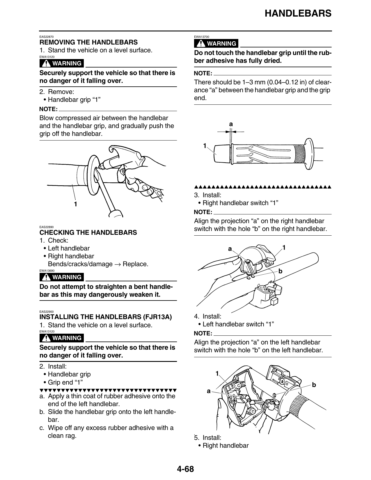
2. Remove: ance “a” between the handlebar grip and the grip
• Handlebar grip “1” end.
NOTE:
Blow compressed air between the handlebar
and the handlebar grip, and gradually push the
grip off the handlebar.
▲▲▲▲▲▲▲▲▲▲▲▲▲▲▲▲▲▲▲▲▲▲▲▲▲▲▲▲▲▲▲▲
3. Install:
• Right handlebar switch “1”
NOTE:
Align the projection “a” on the right handlebar
EAS22890
switch with the hole “b” on the right handlebar.
CHECKING THE HANDLEBARS
1. Check:
• Left handlebar
• Right handlebar
Bends/cracks/damage → Replace.
EWA13690
WARNING
Do not attempt to straighten a bent handle-
bar as this may dangerously weaken it.
EAS22900
INSTALLING THE HANDLEBARS (FJR13A) 4. Install:
1. Stand the vehicle on a level surface. • Left handlebar switch “1”
EWA13120
NOTE:
WARNING
Align the projection “a” on the left handlebar
Securely support the vehicle so that there is switch with the hole “b” on the left handlebar.
no danger of it falling over.
2. Install:
• Handlebar grip
• Grip end “1”
▼▼▼▼▼▼▼▼▼▼▼▼▼▼▼▼▼▼▼▼▼▼▼▼▼▼▼▼▼▼▼▼
a. Apply a thin coat of rubber adhesive onto the
end of the left handlebar.
b. Slide the handlebar grip onto the left handle-
bar.
c. Wipe off any excess rubber adhesive with a
clean rag. 5. Install:
• Right handlebar
4-68
HANDLEBARS
• Left handlebar • There should be 1–3 mm (0.04–0.12 in) of
NOTE: clearance “c” between the throttle grip and the
Fit the projections on each handlebar into the grip end.
holes in the upper bracket, making sure that the
handlebars are installed in the same position.
a a a a
b b b b
c c c c
a. Front position
b. Standard position
c. Rear position
6. Install:
• Handlebar bolts “1”
(temporarily)
• Handlebar nuts “2”
(temporarily) 9. Install:
• Front brake master cylinder assembly
• Front brake master cylinder holder “1”
Front brake master cylinder hold-
T.
R.
er bolt
2 10 Nm (1.0 m·kg, 7.2 ft·lb)
NOTE:
• Install the brake master cylinder holder with the
“UP” mark facing up.
7. Tighten: • Align the mating surfaces of the brake master
• Handlebar bolts cylinder holder with the punch mark “a” on the
• Handlebar nuts right handlebar.
• First, tighten the upper bolt, then the lower bolt.
Handlebar bolt
T.
R.
23 Nm (2.3 m·kg, 17 ft·lb)
Handlebar nut
65 Nm (6.5 m·kg, 47 ft·lb)
NOTE:
First tighten the bolts, then tighten the nuts.
8. Install:
• Throttle grip
• Throttle cables
• Throttle cable housing “1” 10.Install:
• Grip end “2” • Clutch master cylinder assembly
NOTE: • Clutch master cylinder holder “1”
• Align the projection “a” on the throttle cable
housing with the hole “b” in the right handlebar.
4-69