Checking The Balancers
Fragment manuala — str. 430
📋 Tekst do skopiowania / wyszukiwania
BALANCERS
EAS26120
2. Align:
CHECKING THE BALANCERS
• “T” mark on the pickup rotor
1. Check:
(with the crankcase mating surface)
• Front balancer gear
▼▼▼▼▼▼▼▼▼▼▼▼▼▼▼▼▼▼▼▼▼▼▼▼▼▼▼▼▼▼▼▼
Damage/wear → Replace the front balancer a. Turn the crankshaft clockwise.
gear and crankshaft. b. When piston #1 is at TDC on the compres-
• Rear balancer gear sion stroke, align the “T” mark “a” on the pick-
Damage/wear → Replace the rear balancer up rotor with the crankcase mating surface
gear and clutch housing. “b”.
2. Check:
• Balancer shafts
Cracks/damage/wear → Replace the balanc- a
er shaft and bearings.
Dirt → Clean.
• Bearings b
Damage/wear → Replace.
• Dampers
Damage/wear → Replace.
ET3P61032
▲▲▲▲▲▲▲▲▲▲▲▲▲▲▲▲▲▲▲▲▲▲▲▲▲▲▲▲▲▲▲▲
INSTALLING THE FRONT BALANCER
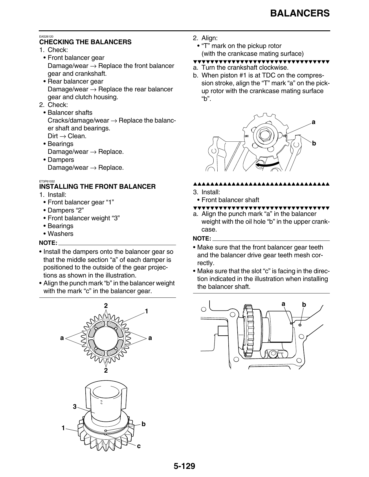
1. Install: 3. Install:
• Front balancer gear “1” • Front balancer shaft
▼▼▼▼▼▼▼▼▼▼▼▼▼▼▼▼▼▼▼▼▼▼▼▼▼▼▼▼▼▼▼▼
• Dampers “2”
a. Align the punch mark “a” in the balancer
• Front balancer weight “3”
weight with the oil hole “b” in the upper crank-
• Bearings
case.
• Washers
NOTE:
NOTE:
• Make sure that the front balancer gear teeth
• Install the dampers onto the balancer gear so
and the balancer drive gear teeth mesh cor-
that the middle section “a” of each damper is
rectly.
positioned to the outside of the gear projec-
• Make sure that the slot “c” is facing in the direc-
tions as shown in the illustration.
tion indicated in the illustration when installing
• Align the punch mark “b” in the balancer weight
the balancer shaft.
with the mark “c” in the balancer gear.
2 a b
a a
b
c
5-129