Checking The Connecting Rods
Fragment manuala — str. 409
📋 Tekst do skopiowania / wyszukiwania
CONNECTING RODS AND PISTONS
ET3P61028
CHECKING THE CONNECTING RODS
1. Measure:
• Crankshaft-pin-to-big-end-bearing clearance 1
Out of specification → Replace the big end
bearings.
Oil clearance (using plasti-
gauge®)
0.031–0.048 mm (0.0012–0.0019
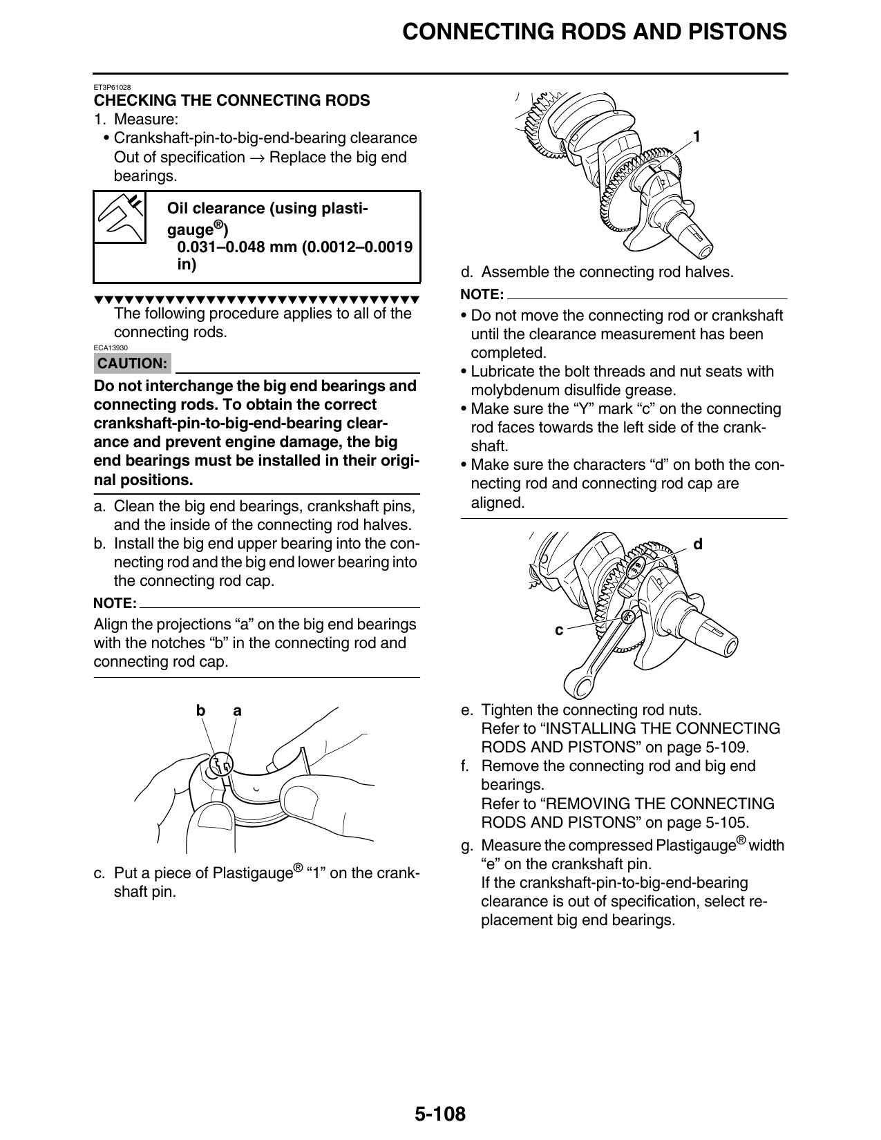
in) d. Assemble the connecting rod halves.
▼▼▼▼▼▼▼▼▼▼▼▼▼▼▼▼▼▼▼▼▼▼▼▼▼▼▼▼▼▼▼▼ NOTE:
The following procedure applies to all of the • Do not move the connecting rod or crankshaft
connecting rods. until the clearance measurement has been
ECA13930
completed.
CAUTION:
• Lubricate the bolt threads and nut seats with
Do not interchange the big end bearings and molybdenum disulfide grease.
connecting rods. To obtain the correct • Make sure the “Y” mark “c” on the connecting
crankshaft-pin-to-big-end-bearing clear- rod faces towards the left side of the crank-
ance and prevent engine damage, the big shaft.
end bearings must be installed in their origi- • Make sure the characters “d” on both the con-
nal positions. necting rod and connecting rod cap are
a. Clean the big end bearings, crankshaft pins, aligned.
and the inside of the connecting rod halves.
b. Install the big end upper bearing into the con- d
necting rod and the big end lower bearing into E
the connecting rod cap.
NOTE:
Align the projections “a” on the big end bearings c
with the notches “b” in the connecting rod and
connecting rod cap.
e. Tighten the connecting rod nuts.
Refer to “INSTALLING THE CONNECTING
RODS AND PISTONS” on page 5-109.
f. Remove the connecting rod and big end
bearings.
Refer to “REMOVING THE CONNECTING
RODS AND PISTONS” on page 5-105.
g. Measure the compressed Plastigauge® width
“e” on the crankshaft pin.
c. Put a piece of Plastigauge® “1” on the crank-
If the crankshaft-pin-to-big-end-bearing
shaft pin.
clearance is out of specification, select re-
placement big end bearings.
5-108