Installing The Connecting Rods And Pistons
Fragment manuala — str. 410–412
📋 Tekst do skopiowania / wyszukiwania
CONNECTING RODS AND PISTONS
For example, if the connecting rod P1 and the
crankshaft web P1 numbers are 6 and 1 re-
spectively, then the bearing size for P1 is:
P1 (connecting rod) - P1 (crankshaft)
=
6 - 1 = 5 (yellow)
e
Bearing color code
1.Blue 2.Black 3.Brown 4.Green
▲▲▲▲▲▲▲▲▲▲▲▲▲▲▲▲▲▲▲▲▲▲▲▲▲▲▲▲▲▲▲▲ 5.Yellow 6.Pink
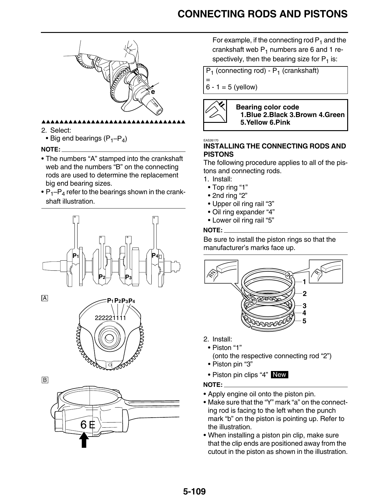
2. Select:
• Big end bearings (P1–P4) EAS26170
NOTE:
INSTALLING THE CONNECTING RODS AND
PISTONS
• The numbers “A” stamped into the crankshaft
The following procedure applies to all of the pis-
web and the numbers “B” on the connecting
tons and connecting rods.
rods are used to determine the replacement
1. Install:
big end bearing sizes.
• Top ring “1”
• P1–P4 refer to the bearings shown in the crank-
• 2nd ring “2”
shaft illustration. • Upper oil ring rail “3”
• Oil ring expander “4”
• Lower oil ring rail “5”
NOTE:
Be sure to install the piston rings so that the
manufacturer’s marks face up.
P1 P4
P2 P3
A P1 P2 P3 P4
2. Install:
• Piston “1”
(onto the respective connecting rod “2”)
• Piston pin “3”
• Piston pin clips “4” New
B
NOTE:
• Apply engine oil onto the piston pin.
• Make sure that the “Y” mark “a” on the connect-
ing rod is facing to the left when the punch
mark “b” on the piston is pointing up. Refer to
E the illustration.
• When installing a piston pin clip, make sure
that the clip ends are positioned away from the
cutout in the piston as shown in the illustration.
5-109
CONNECTING RODS AND PISTONS
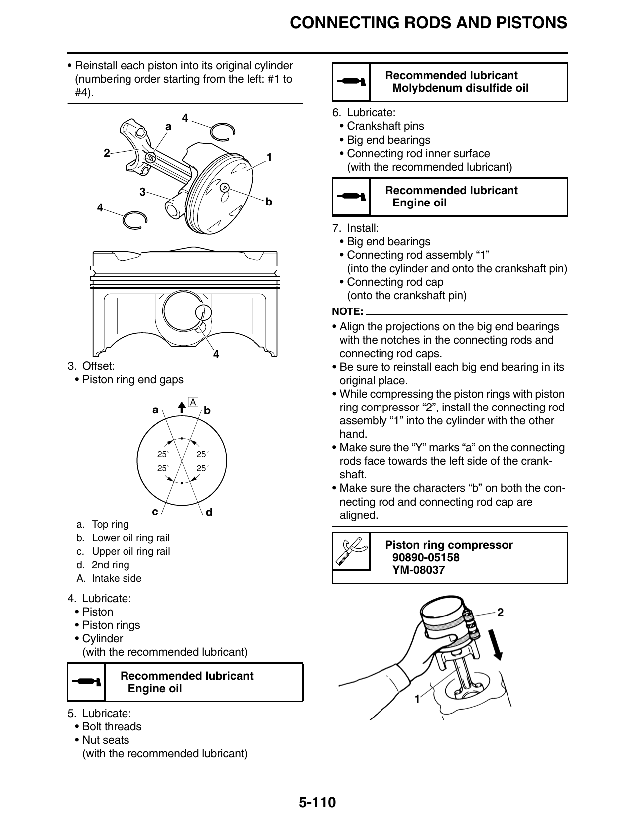
• Reinstall each piston into its original cylinder
(numbering order starting from the left: #1 to Recommended lubricant
#4). Molybdenum disulfide oil
4 6. Lubricate:
a • Crankshaft pins
• Big end bearings
2 1 • Connecting rod inner surface
(with the recommended lubricant)
3 Recommended lubricant
b Engine oil
7. Install:
• Big end bearings
• Connecting rod assembly “1”
(into the cylinder and onto the crankshaft pin)
• Connecting rod cap
(onto the crankshaft pin)
NOTE:
• Align the projections on the big end bearings
with the notches in the connecting rods and
4 connecting rod caps.
3. Offset: • Be sure to reinstall each big end bearing in its
• Piston ring end gaps original place.
• While compressing the piston rings with piston
ring compressor “2”, install the connecting rod
assembly “1” into the cylinder with the other
hand.
• Make sure the “Y” marks “a” on the connecting
rods face towards the left side of the crank-
shaft.
• Make sure the characters “b” on both the con-
necting rod and connecting rod cap are
aligned.
a. Top ring
b. Lower oil ring rail
Piston ring compressor
c. Upper oil ring rail
90890-05158
d. 2nd ring
YM-08037
A. Intake side
4. Lubricate:
• Piston
• Piston rings
• Cylinder
(with the recommended lubricant)
Recommended lubricant
Engine oil
5. Lubricate:
• Bolt threads
• Nut seats
(with the recommended lubricant)
5-110
CONNECTING RODS AND PISTONS
EWA13400
b 6E
WARNING
a If the connecting rod nut is tightened more
than the specified angle, do not loosen the
nut and then retighten it. Instead, replace the
connecting rod bolt and nut with a new one
and perform the procedure again.
ECA13950
CAUTION:
Do not use a torque wrench to tighten the
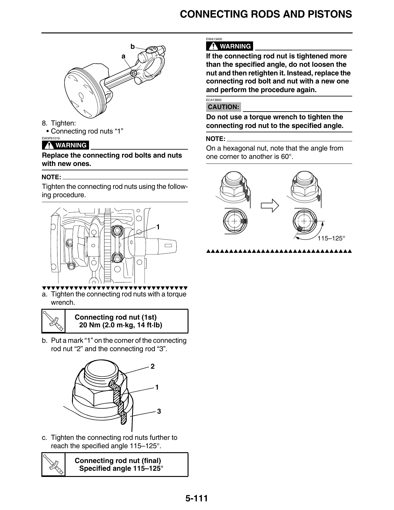
8. Tighten: connecting rod nut to the specified angle.
• Connecting rod nuts “1”
EW3P61019 NOTE:
WARNING On a hexagonal nut, note that the angle from
Replace the connecting rod bolts and nuts one corner to another is 60°.
with new ones.
NOTE:
Tighten the connecting rod nuts using the follow-
ing procedure.
▲▲▲▲▲▲▲▲▲▲▲▲▲▲▲▲▲▲▲▲▲▲▲▲▲▲▲▲▲▲▲▲
▼▼▼▼▼▼▼▼▼▼▼▼▼▼▼▼▼▼▼▼▼▼▼▼▼▼▼▼▼▼▼▼
a. Tighten the connecting rod nuts with a torque
wrench.
Connecting rod nut (1st)
T.
R.
20 Nm (2.0 m·kg, 14 ft·lb)
b. Put a mark “1” on the corner of the connecting
rod nut “2” and the connecting rod “3”.
c. Tighten the connecting rod nuts further to
reach the specified angle 115–125°.
Connecting rod nut (final)
T.
R.
Specified angle 115–125°
5-111