Installing The Camshafts
Fragment manuala — str. 318–321
📋 Tekst do skopiowania / wyszukiwania
CAMSHAFTS
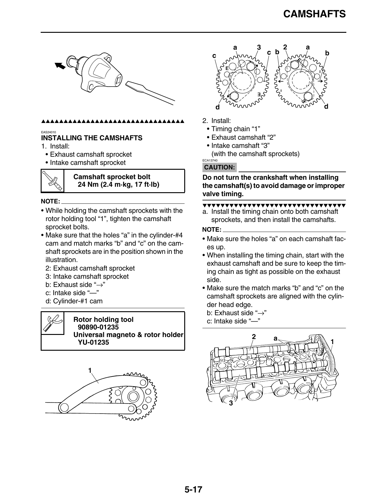
▲▲▲▲▲▲▲▲▲▲▲▲▲▲▲▲▲▲▲▲▲▲▲▲▲▲▲▲▲▲▲▲ 2. Install:
EAS24010
• Timing chain “1”
INSTALLING THE CAMSHAFTS • Exhaust camshaft “2”
1. Install: • Intake camshaft “3”
• Exhaust camshaft sprocket (with the camshaft sprockets)
ECA13740
• Intake camshaft sprocket
CAUTION:
Camshaft sprocket bolt Do not turn the crankshaft when installing
T.
R.
24 Nm (2.4 m·kg, 17 ft·lb) the camshaft(s) to avoid damage or improper
valve timing.
NOTE:
▼▼▼▼▼▼▼▼▼▼▼▼▼▼▼▼▼▼▼▼▼▼▼▼▼▼▼▼▼▼▼▼
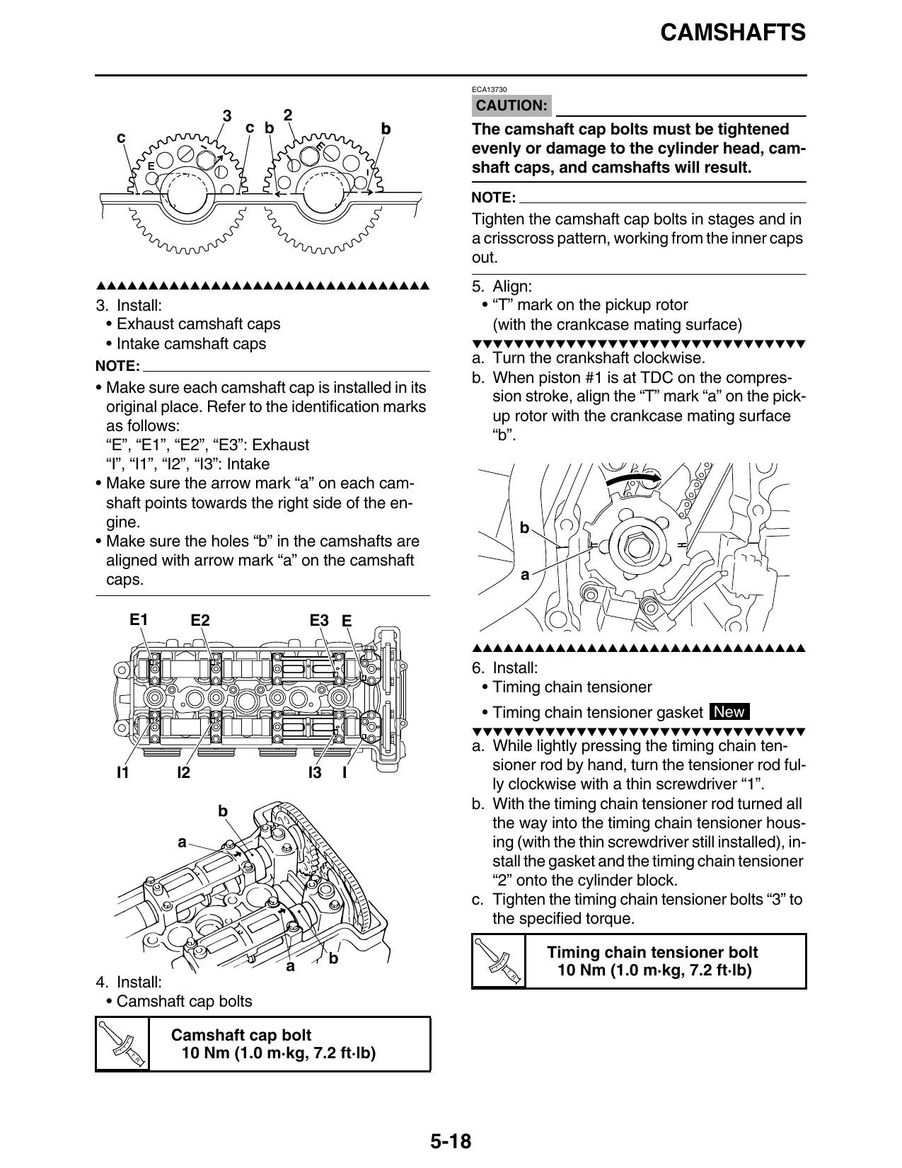
• While holding the camshaft sprockets with the a. Install the timing chain onto both camshaft
rotor holding tool “1”, tighten the camshaft sprockets, and then install the camshafts.
sprocket bolts. NOTE:
• Make sure that the holes “a” in the cylinder-#4
• Make sure the holes “a” on each camshaft fac-
cam and match marks “b” and “c” on the cam-
es up.
shaft sprockets are in the position shown in the
• When installing the timing chain, start with the
illustration.
exhaust camshaft and be sure to keep the tim-
2: Exhaust camshaft sprocket
ing chain as tight as possible on the exhaust
3: Intake camshaft sprocket
side.
b: Exhaust side “→”
• Make sure the match marks “b” and “c” on the
c: Intake side “—”
camshaft sprockets are aligned with the cylin-
d: Cylinder-#1 cam
der head edge.
b: Exhaust side “→”
Rotor holding tool c: Intake side “—”
90890-01235
Universal magneto & rotor holder
YU-01235
5-17
CAMSHAFTS
ECA13730
CAUTION:
The camshaft cap bolts must be tightened
evenly or damage to the cylinder head, cam-
shaft caps, and camshafts will result.
NOTE:
Tighten the camshaft cap bolts in stages and in
a crisscross pattern, working from the inner caps
out.
▲▲▲▲▲▲▲▲▲▲▲▲▲▲▲▲▲▲▲▲▲▲▲▲▲▲▲▲▲▲▲▲ 5. Align:
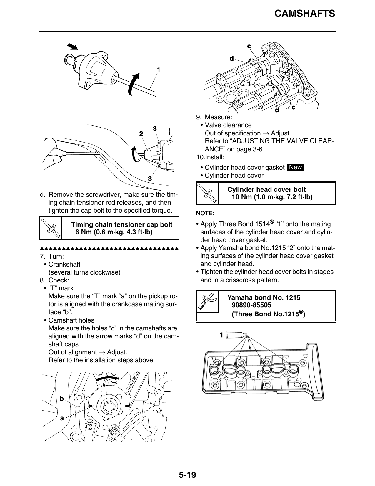
3. Install: • “T” mark on the pickup rotor
• Exhaust camshaft caps (with the crankcase mating surface)
• Intake camshaft caps ▼▼▼▼▼▼▼▼▼▼▼▼▼▼▼▼▼▼▼▼▼▼▼▼▼▼▼▼▼▼▼▼
NOTE:
a. Turn the crankshaft clockwise.
b. When piston #1 is at TDC on the compres-
• Make sure each camshaft cap is installed in its
sion stroke, align the “T” mark “a” on the pick-
original place. Refer to the identification marks
up rotor with the crankcase mating surface
as follows:
“b”.
“E”, “E1”, “E2”, “E3”: Exhaust
“I”, “I1”, “I2”, “I3”: Intake
• Make sure the arrow mark “a” on each cam-
shaft points towards the right side of the en-
gine. b
• Make sure the holes “b” in the camshafts are
aligned with arrow mark “a” on the camshaft
caps. a
E1 E2 E3 E
▲▲▲▲▲▲▲▲▲▲▲▲▲▲▲▲▲▲▲▲▲▲▲▲▲▲▲▲▲▲▲▲
6. Install:
• Timing chain tensioner
• Timing chain tensioner gasket New
▼▼▼▼▼▼▼▼▼▼▼▼▼▼▼▼▼▼▼▼▼▼▼▼▼▼▼▼▼▼▼▼
a. While lightly pressing the timing chain ten-
I1 I2 I3 I sioner rod by hand, turn the tensioner rod ful-
ly clockwise with a thin screwdriver “1”.
b. With the timing chain tensioner rod turned all
the way into the timing chain tensioner hous-
ing (with the thin screwdriver still installed), in-
stall the gasket and the timing chain tensioner
“2” onto the cylinder block.
c. Tighten the timing chain tensioner bolts “3” to
the specified torque.
Timing chain tensioner bolt
T. 10 Nm (1.0 m·kg, 7.2 ft·lb)
4. Install: R.
• Camshaft cap bolts
Camshaft cap bolt
T.
R.
10 Nm (1.0 m·kg, 7.2 ft·lb)
5-18
CAMSHAFTS
9. Measure:
• Valve clearance
Out of specification → Adjust.
Refer to “ADJUSTING THE VALVE CLEAR-
ANCE” on page 3-6.
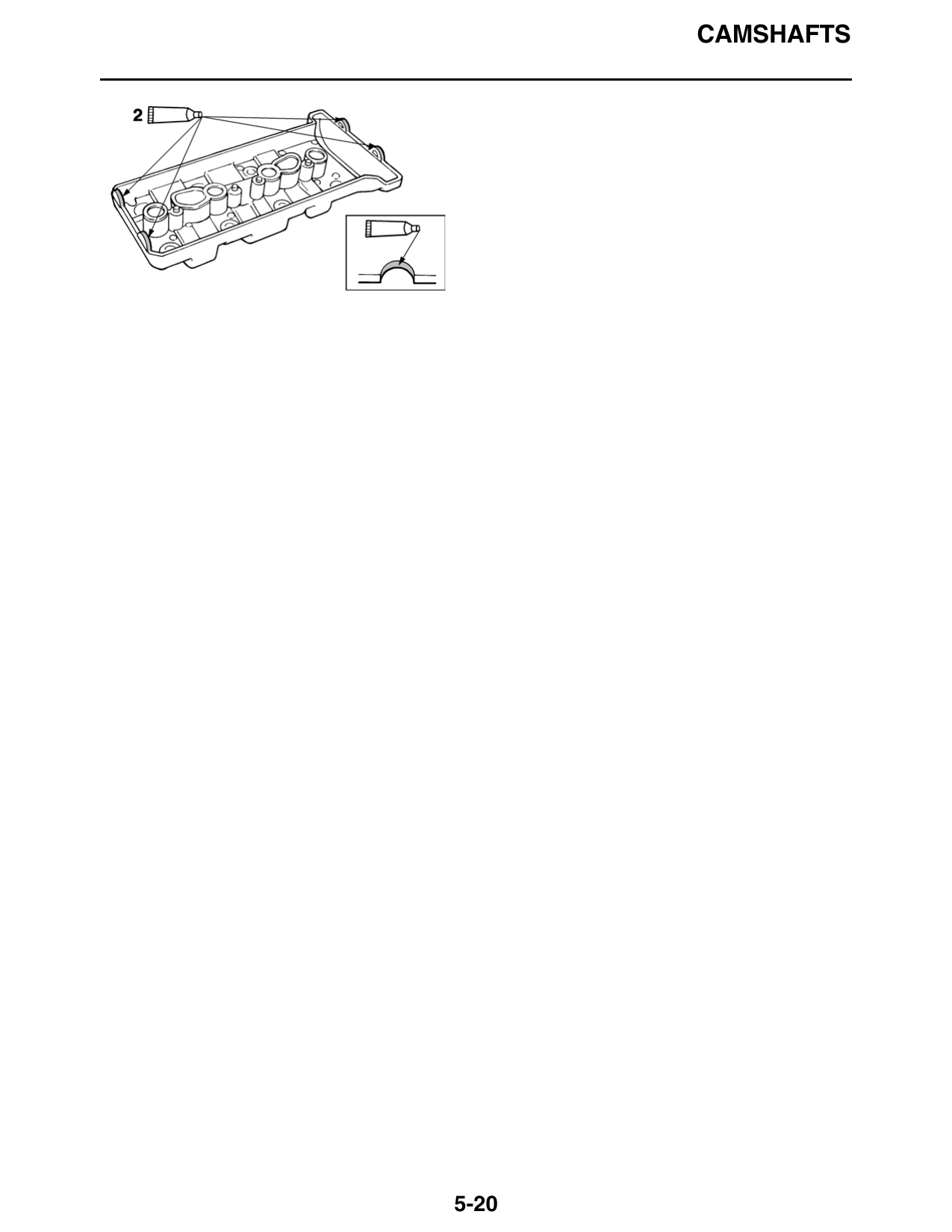
10.Install:
• Cylinder head cover gasket New
• Cylinder head cover
Cylinder head cover bolt
d. Remove the screwdriver, make sure the tim- T. 10 Nm (1.0 m·kg, 7.2 ft·lb)
ing chain tensioner rod releases, and then
R.
tighten the cap bolt to the specified torque. NOTE:
Timing chain tensioner cap bolt • Apply Three Bond 1514® “1” onto the mating
T.
R.
6 Nm (0.6 m·kg, 4.3 ft·lb) surfaces of the cylinder head cover and cylin-
der head cover gasket.
▲▲▲▲▲▲▲▲▲▲▲▲▲▲▲▲▲▲▲▲▲▲▲▲▲▲▲▲▲▲▲▲ • Apply Yamaha bond No.1215 “2” onto the mat-
7. Turn: ing surfaces of the cylinder head cover gasket
• Crankshaft and cylinder head.
(several turns clockwise) • Tighten the cylinder head cover bolts in stages
8. Check: and in a crisscross pattern.
• “T” mark
Make sure the “T” mark “a” on the pickup ro- Yamaha bond No. 1215
tor is aligned with the crankcase mating sur- 90890-85505
face “b”. (Three Bond No.1215®)
• Camshaft holes
Make sure the holes “c” in the camshafts are
aligned with the arrow marks “d” on the cam-
shaft caps.
Out of alignment → Adjust.
Refer to the installation steps above.
b
a
5-19
CAMSHAFTS
5-20