Installing The Crankshaft
Fragment manuala — str. 415–416
📋 Tekst do skopiowania / wyszukiwania
CRANKSHAFT
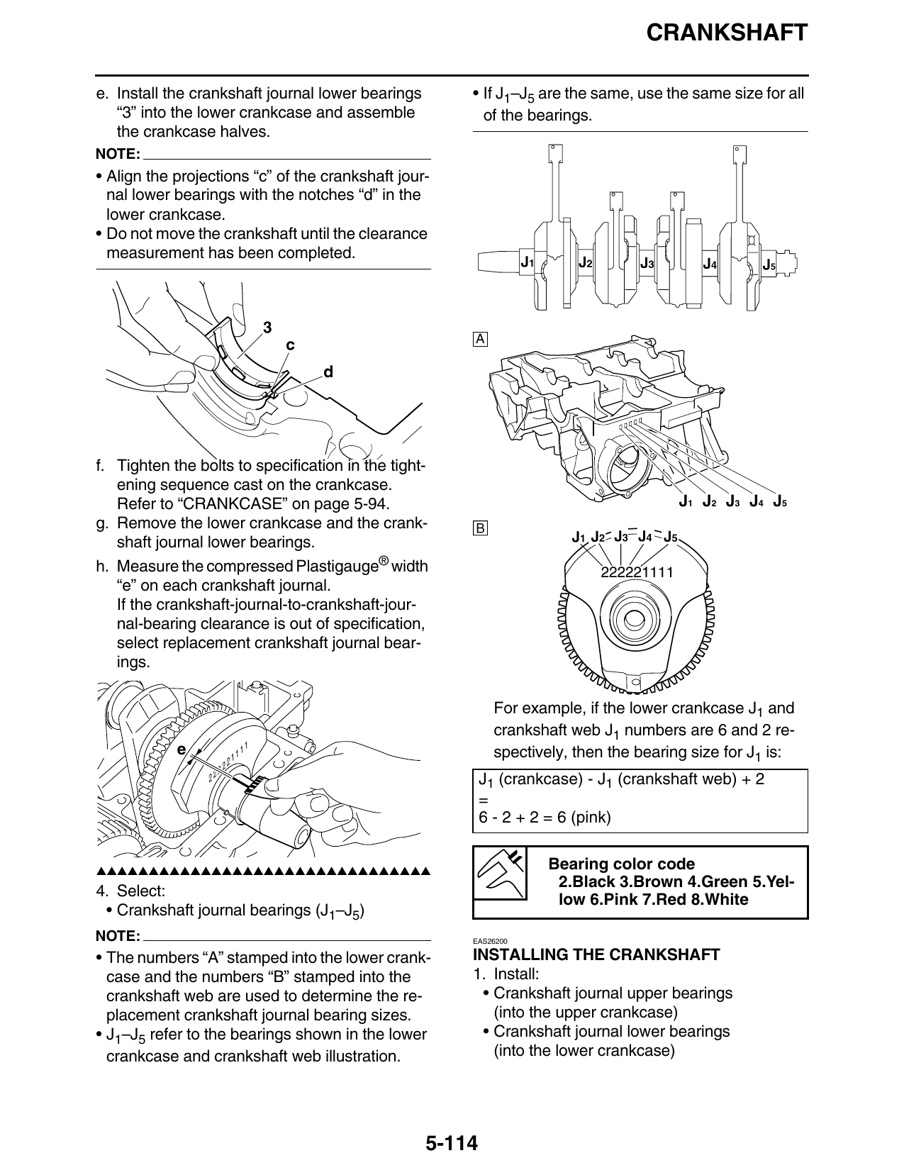
e. Install the crankshaft journal lower bearings • If J1–J5 are the same, use the same size for all
“3” into the lower crankcase and assemble of the bearings.
the crankcase halves.
NOTE:
• Align the projections “c” of the crankshaft jour-
nal lower bearings with the notches “d” in the
lower crankcase.
• Do not move the crankshaft until the clearance
measurement has been completed.
A
f. Tighten the bolts to specification in the tight-
ening sequence cast on the crankcase.
Refer to “CRANKCASE” on page 5-94. J1 J2 J3 J4 J5
g. Remove the lower crankcase and the crank-
shaft journal lower bearings.
h. Measure the compressed Plastigauge® width
“e” on each crankshaft journal.
If the crankshaft-journal-to-crankshaft-jour-
nal-bearing clearance is out of specification,
select replacement crankshaft journal bear-
ings.
For example, if the lower crankcase J1 and
crankshaft web J1 numbers are 6 and 2 re-
e 11 spectively, then the bearing size for J1 is:
2 11
22 J1 (crankcase) - J1 (crankshaft web) + 2
=
6 - 2 + 2 = 6 (pink)
▲▲▲▲▲▲▲▲▲▲▲▲▲▲▲▲▲▲▲▲▲▲▲▲▲▲▲▲▲▲▲▲ Bearing color code
2.Black 3.Brown 4.Green 5.Yel-
4. Select:
low 6.Pink 7.Red 8.White
• Crankshaft journal bearings (J1–J5)
NOTE: EAS26200
• The numbers “A” stamped into the lower crank- INSTALLING THE CRANKSHAFT
case and the numbers “B” stamped into the 1. Install:
crankshaft web are used to determine the re- • Crankshaft journal upper bearings
placement crankshaft journal bearing sizes. (into the upper crankcase)
• J1–J5 refer to the bearings shown in the lower • Crankshaft journal lower bearings
crankcase and crankshaft web illustration. (into the lower crankcase)
5-114
CRANKSHAFT
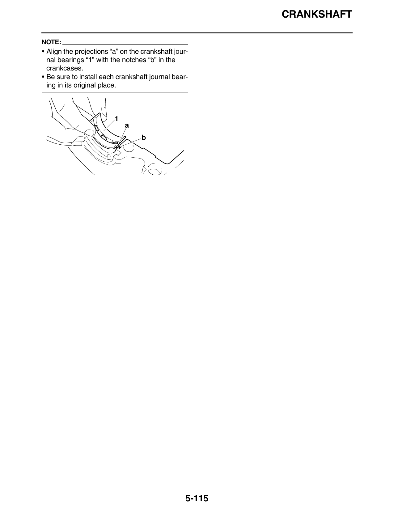
NOTE:
• Align the projections “a” on the crankshaft jour-
nal bearings “1” with the notches “b” in the
crankcases.
• Be sure to install each crankshaft journal bear-
ing in its original place.
5-115