Installing The Cylinder Head
Fragment manuala — str. 323–324
📋 Tekst do skopiowania / wyszukiwania
CYLINDER HEAD
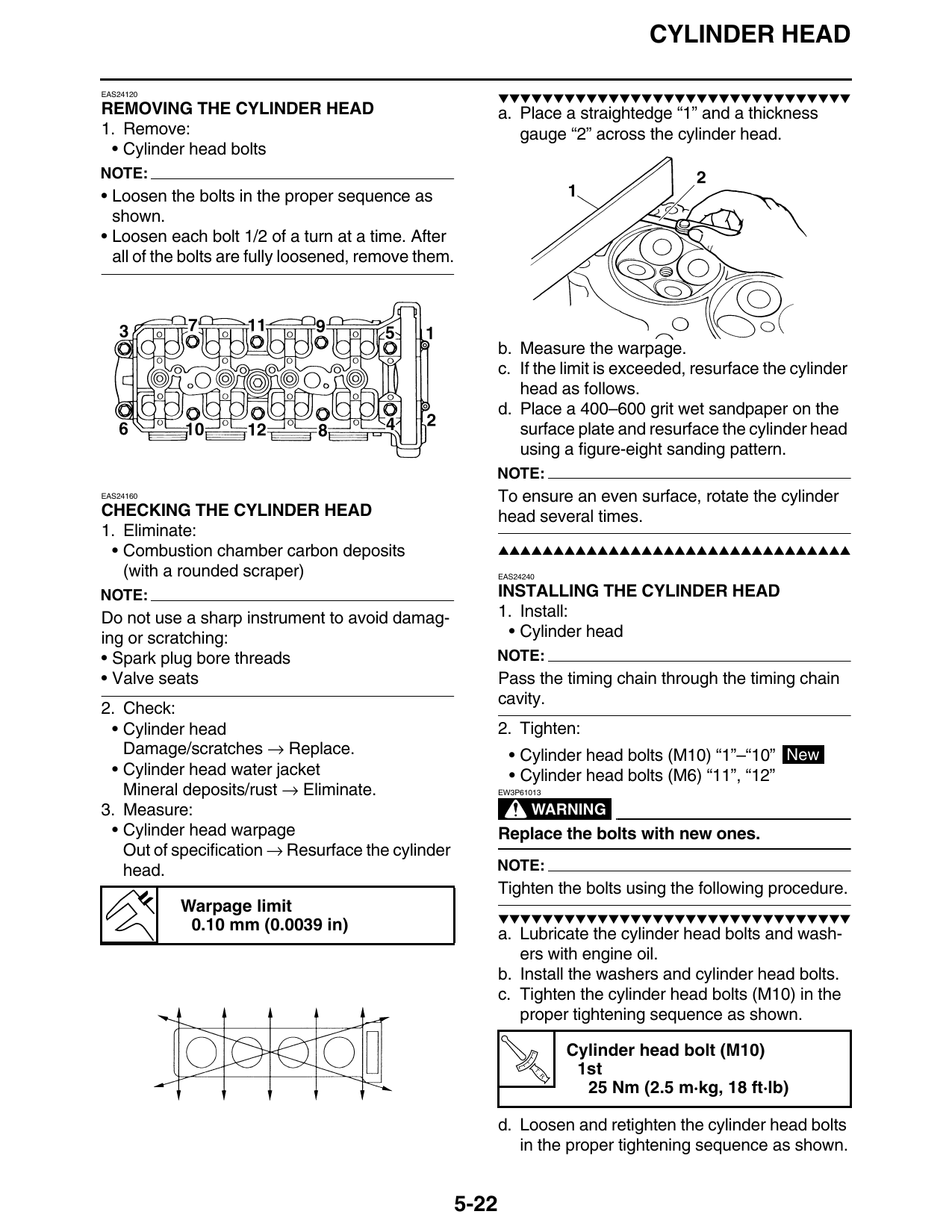
EAS24120
▼▼▼▼▼▼▼▼▼▼▼▼▼▼▼▼▼▼▼▼▼▼▼▼▼▼▼▼▼▼▼▼
REMOVING THE CYLINDER HEAD a. Place a straightedge “1” and a thickness
1. Remove: gauge “2” across the cylinder head.
• Cylinder head bolts
NOTE:
• Loosen the bolts in the proper sequence as
shown.
• Loosen each bolt 1/2 of a turn at a time. After
all of the bolts are fully loosened, remove them.
b. Measure the warpage.
c. If the limit is exceeded, resurface the cylinder
head as follows.
d. Place a 400–600 grit wet sandpaper on the
surface plate and resurface the cylinder head
using a figure-eight sanding pattern.
NOTE:
EAS24160 To ensure an even surface, rotate the cylinder
CHECKING THE CYLINDER HEAD head several times.
1. Eliminate:
• Combustion chamber carbon deposits ▲▲▲▲▲▲▲▲▲▲▲▲▲▲▲▲▲▲▲▲▲▲▲▲▲▲▲▲▲▲▲▲
(with a rounded scraper) EAS24240
NOTE: INSTALLING THE CYLINDER HEAD
Do not use a sharp instrument to avoid damag- 1. Install:
ing or scratching: • Cylinder head
• Spark plug bore threads NOTE:
• Valve seats Pass the timing chain through the timing chain
cavity.
2. Check:
• Cylinder head 2. Tighten:
Damage/scratches → Replace. • Cylinder head bolts (M10) “1”–“10” New
• Cylinder head water jacket • Cylinder head bolts (M6) “11”, “12”
Mineral deposits/rust → Eliminate. EW3P61013
3. Measure: WARNING
• Cylinder head warpage Replace the bolts with new ones.
Out of specification → Resurface the cylinder
head. NOTE:
Tighten the bolts using the following procedure.
Warpage limit
▼▼▼▼▼▼▼▼▼▼▼▼▼▼▼▼▼▼▼▼▼▼▼▼▼▼▼▼▼▼▼▼
0.10 mm (0.0039 in)
a. Lubricate the cylinder head bolts and wash-
ers with engine oil.
b. Install the washers and cylinder head bolts.
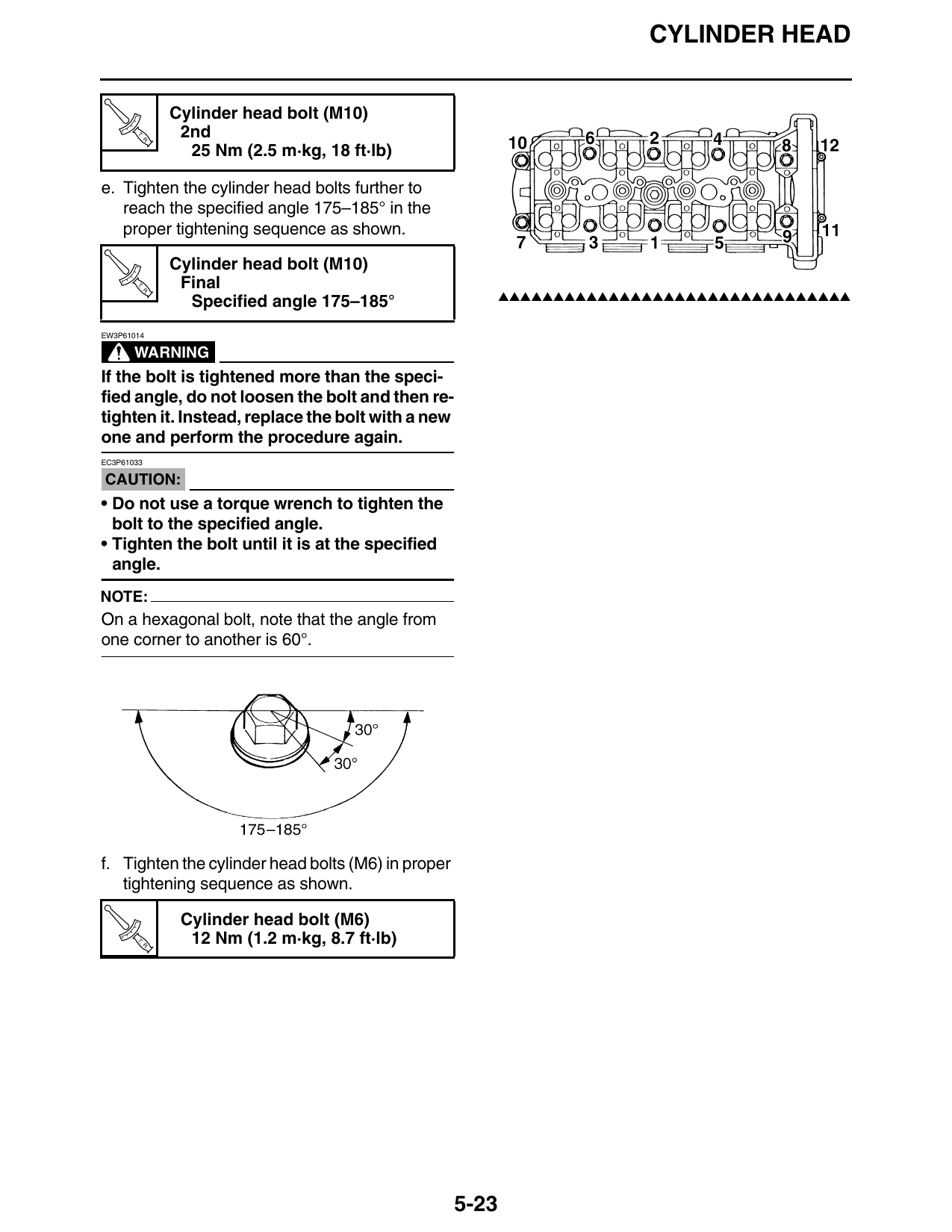
c. Tighten the cylinder head bolts (M10) in the
proper tightening sequence as shown.
Cylinder head bolt (M10)
T.
R.
1st
25 Nm (2.5 m·kg, 18 ft·lb)
d. Loosen and retighten the cylinder head bolts
in the proper tightening sequence as shown.
5-22
CYLINDER HEAD
Cylinder head bolt (M10)
T.
R.
2nd
25 Nm (2.5 m·kg, 18 ft·lb)
e. Tighten the cylinder head bolts further to
reach the specified angle 175–185° in the
proper tightening sequence as shown.
Cylinder head bolt (M10)
T. Final
▲▲▲▲▲▲▲▲▲▲▲▲▲▲▲▲▲▲▲▲▲▲▲▲▲▲▲▲▲▲▲▲
R.
Specified angle 175–185°
EW3P61014
WARNING
If the bolt is tightened more than the speci-
fied angle, do not loosen the bolt and then re-
tighten it. Instead, replace the bolt with a new
one and perform the procedure again.
EC3P61033
CAUTION:
• Do not use a torque wrench to tighten the
bolt to the specified angle.
• Tighten the bolt until it is at the specified
angle.
NOTE:
On a hexagonal bolt, note that the angle from
one corner to another is 60°.
f. Tighten the cylinder head bolts (M6) in proper
tightening sequence as shown.
Cylinder head bolt (M6)
T.
R.
12 Nm (1.2 m·kg, 8.7 ft·lb)
5-23