Installing The Rear Balancer
Fragment manuala — str. 431–434

📋 Tekst do skopiowania / wyszukiwania
BALANCERS
Front balancer lever bolt
T.
R.
14 Nm (1.4 m·kg, 10 ft·lb)
Front balancer shaft pinch bolt
10 Nm (1.0 m·kg, 7.2 ft·lb)
NOTE:
Make sure that the balancer shaft does not ro-
c tate.
▲▲▲▲▲▲▲▲▲▲▲▲▲▲▲▲▲▲▲▲▲▲▲▲▲▲▲▲▲▲▲▲
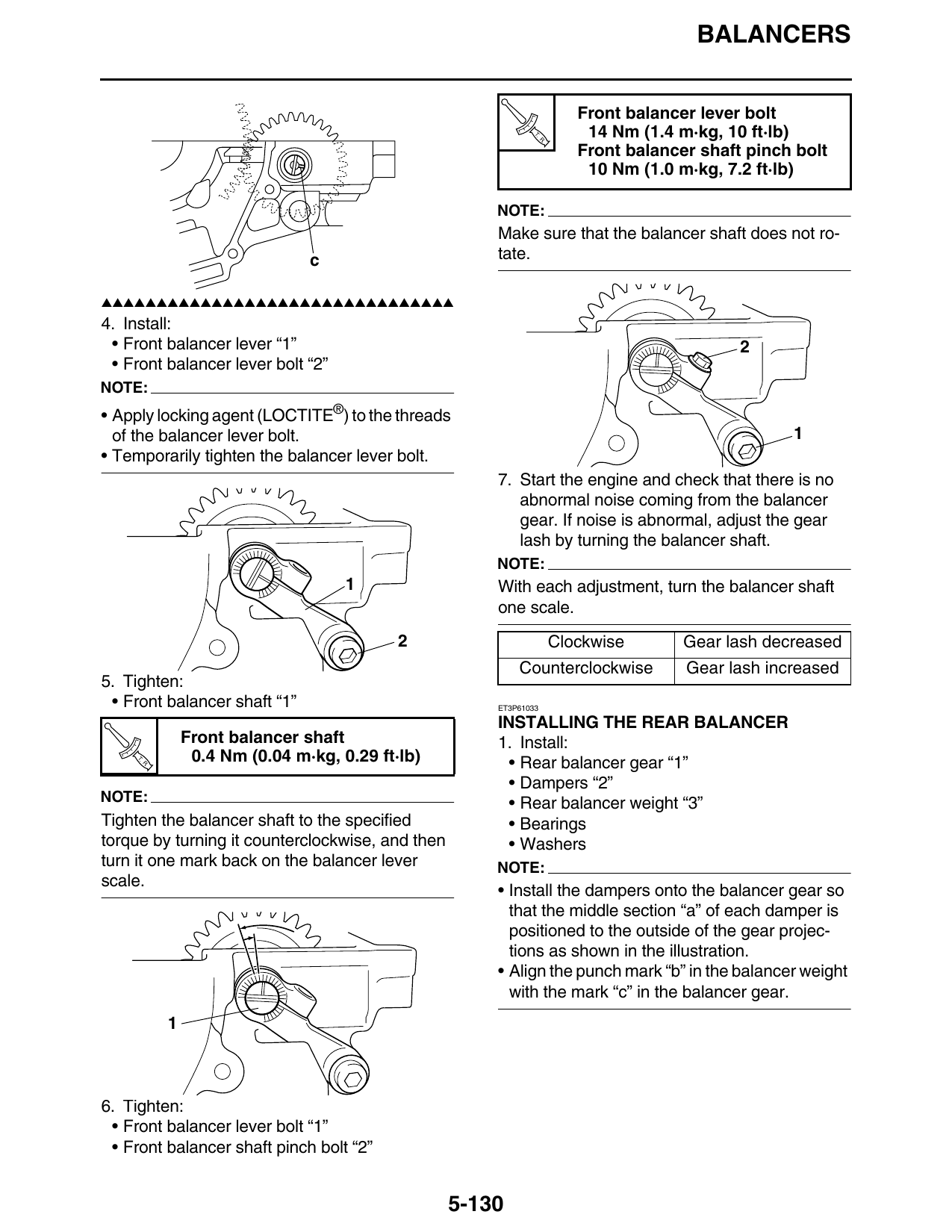
4. Install:
• Front balancer lever “1” 2
• Front balancer lever bolt “2”
NOTE:
• Apply locking agent (LOCTITE®) to the threads
of the balancer lever bolt. 1
• Temporarily tighten the balancer lever bolt.
7. Start the engine and check that there is no
abnormal noise coming from the balancer
gear. If noise is abnormal, adjust the gear
lash by turning the balancer shaft.
NOTE:
1 With each adjustment, turn the balancer shaft
one scale.
2 Clockwise Gear lash decreased
Counterclockwise Gear lash increased
5. Tighten:
• Front balancer shaft “1” ET3P61033
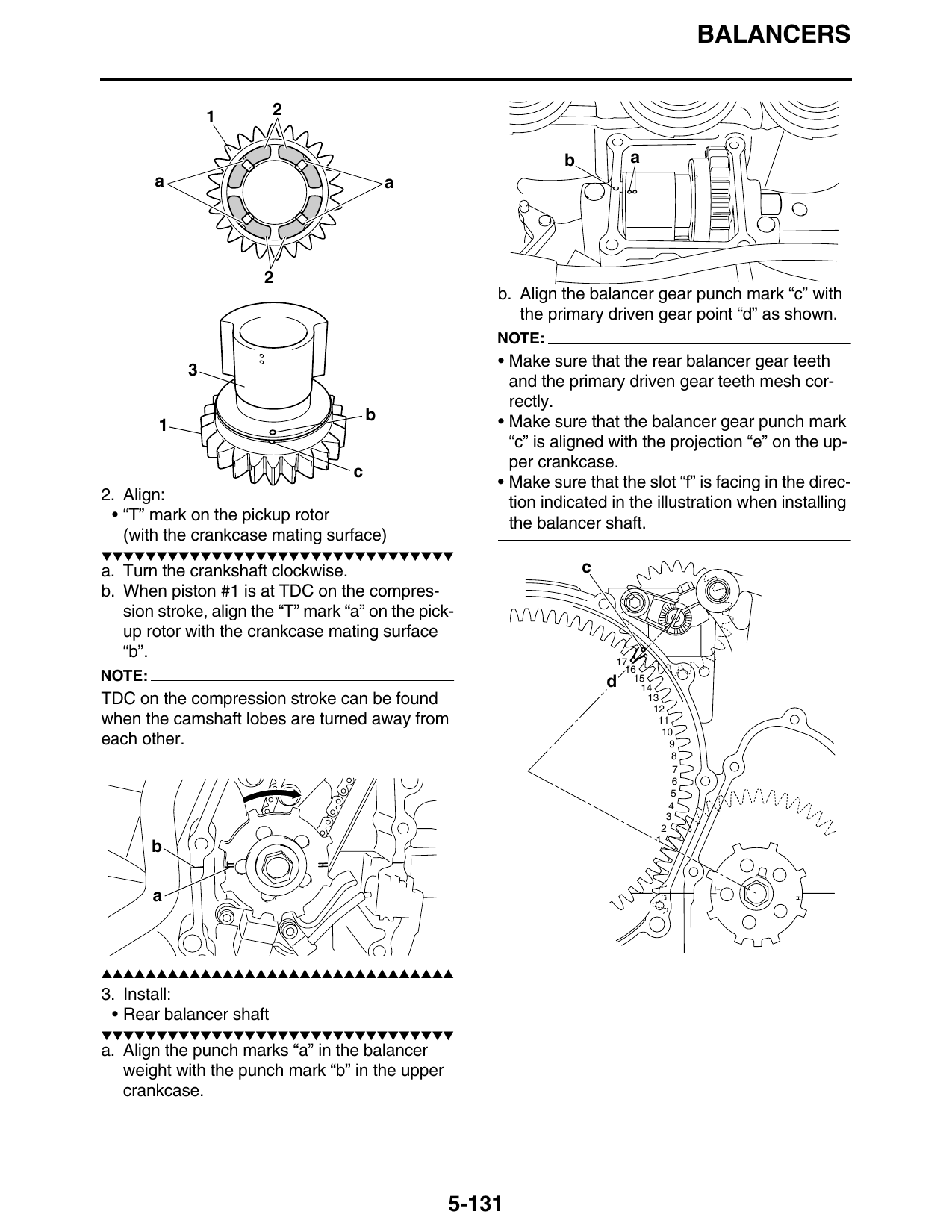
INSTALLING THE REAR BALANCER
Front balancer shaft 1. Install:
T.
R.
0.4 Nm (0.04 m·kg, 0.29 ft·lb) • Rear balancer gear “1”
• Dampers “2”
NOTE: • Rear balancer weight “3”
Tighten the balancer shaft to the specified • Bearings
torque by turning it counterclockwise, and then • Washers
turn it one mark back on the balancer lever NOTE:
scale.
• Install the dampers onto the balancer gear so
that the middle section “a” of each damper is
positioned to the outside of the gear projec-
tions as shown in the illustration.
• Align the punch mark “b” in the balancer weight
with the mark “c” in the balancer gear.
6. Tighten:
• Front balancer lever bolt “1”
• Front balancer shaft pinch bolt “2”
5-130
BALANCERS
1 2
b a
a a
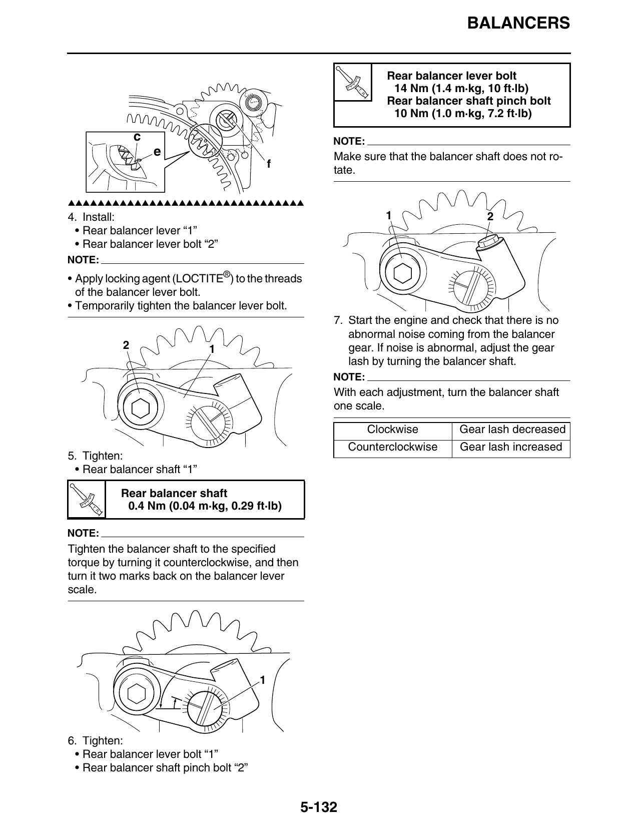
b. Align the balancer gear punch mark “c” with
the primary driven gear point “d” as shown.
NOTE:
• Make sure that the rear balancer gear teeth
and the primary driven gear teeth mesh cor-
rectly.
b • Make sure that the balancer gear punch mark
“c” is aligned with the projection “e” on the up-
per crankcase.
c
• Make sure that the slot “f” is facing in the direc-
2. Align: tion indicated in the illustration when installing
• “T” mark on the pickup rotor the balancer shaft.
(with the crankcase mating surface)
▼▼▼▼▼▼▼▼▼▼▼▼▼▼▼▼▼▼▼▼▼▼▼▼▼▼▼▼▼▼▼▼
a. Turn the crankshaft clockwise. c
b. When piston #1 is at TDC on the compres-
sion stroke, align the “T” mark “a” on the pick-
up rotor with the crankcase mating surface
“b”. 17
NOTE: d 15
TDC on the compression stroke can be found 13
when the camshaft lobes are turned away from 11
each other. 9
b
a
▲▲▲▲▲▲▲▲▲▲▲▲▲▲▲▲▲▲▲▲▲▲▲▲▲▲▲▲▲▲▲▲
3. Install:
• Rear balancer shaft
▼▼▼▼▼▼▼▼▼▼▼▼▼▼▼▼▼▼▼▼▼▼▼▼▼▼▼▼▼▼▼▼
a. Align the punch marks “a” in the balancer
weight with the punch mark “b” in the upper
crankcase.
5-131
BALANCERS
Rear balancer lever bolt
T.
R.
14 Nm (1.4 m·kg, 10 ft·lb)
Rear balancer shaft pinch bolt
10 Nm (1.0 m·kg, 7.2 ft·lb)
c NOTE:
e Make sure that the balancer shaft does not ro-
f
tate.
▲▲▲▲▲▲▲▲▲▲▲▲▲▲▲▲▲▲▲▲▲▲▲▲▲▲▲▲▲▲▲▲
4. Install: 1 2
• Rear balancer lever “1”
• Rear balancer lever bolt “2”
NOTE:
• Apply locking agent (LOCTITE®) to the threads
of the balancer lever bolt.
• Temporarily tighten the balancer lever bolt.
7. Start the engine and check that there is no
abnormal noise coming from the balancer
2 1 gear. If noise is abnormal, adjust the gear
lash by turning the balancer shaft.
NOTE:
With each adjustment, turn the balancer shaft
one scale.
Clockwise Gear lash decreased
Counterclockwise Gear lash increased
5. Tighten:
• Rear balancer shaft “1”
Rear balancer shaft
T.
R.
0.4 Nm (0.04 m·kg, 0.29 ft·lb)
NOTE:
Tighten the balancer shaft to the specified
torque by turning it counterclockwise, and then
turn it two marks back on the balancer lever
scale.
6. Tighten:
• Rear balancer lever bolt “1”
• Rear balancer shaft pinch bolt “2”
5-132
BALANCERS
5-133