Installing The Shift Actuator
Fragment manuala — str. 372–373
📋 Tekst do skopiowania / wyszukiwania
SHIFT ACTUATOR AND SHIFT ROD (FJR13AE only)
Shift actuator rear bolt
2 T. 20 Nm (2.0 m·kg, 14 ft·lb)
3 R.
Shift actuator front bolt
20 Nm (2.0 m·kg, 14 ft·lb)
▲▲▲▲▲▲▲▲▲▲▲▲▲▲▲▲▲▲▲▲▲▲▲▲▲▲▲▲▲▲▲▲
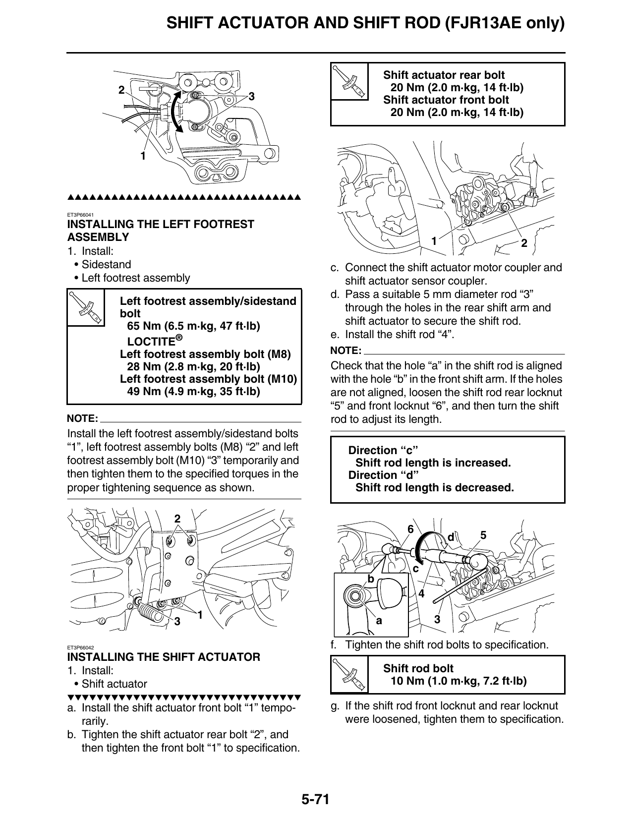
ET3P66041
INSTALLING THE LEFT FOOTREST
ASSEMBLY 1 2
1. Install:
• Sidestand c. Connect the shift actuator motor coupler and
• Left footrest assembly shift actuator sensor coupler.
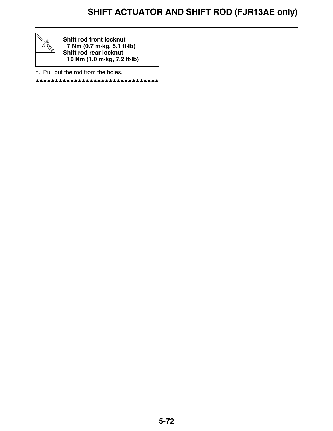
d. Pass a suitable 5 mm diameter rod “3”
Left footrest assembly/sidestand
through the holes in the rear shift arm and
T. bolt
R.
65 Nm (6.5 m·kg, 47 ft·lb) shift actuator to secure the shift rod.
e. Install the shift rod “4”.
LOCTITE®
Left footrest assembly bolt (M8) NOTE:
28 Nm (2.8 m·kg, 20 ft·lb) Check that the hole “a” in the shift rod is aligned
Left footrest assembly bolt (M10) with the hole “b” in the front shift arm. If the holes
49 Nm (4.9 m·kg, 35 ft·lb) are not aligned, loosen the shift rod rear locknut
“5” and front locknut “6”, and then turn the shift
NOTE: rod to adjust its length.
Install the left footrest assembly/sidestand bolts
“1”, left footrest assembly bolts (M8) “2” and left Direction “c”
footrest assembly bolt (M10) “3” temporarily and Shift rod length is increased.
then tighten them to the specified torques in the Direction “d”
proper tightening sequence as shown. Shift rod length is decreased.
d 5
c
b
1 a 3
ET3P66042 f. Tighten the shift rod bolts to specification.
INSTALLING THE SHIFT ACTUATOR
1. Install: Shift rod bolt
• Shift actuator T.
R.
10 Nm (1.0 m·kg, 7.2 ft·lb)
▼▼▼▼▼▼▼▼▼▼▼▼▼▼▼▼▼▼▼▼▼▼▼▼▼▼▼▼▼▼▼▼
a. Install the shift actuator front bolt “1” tempo- g. If the shift rod front locknut and rear locknut
rarily. were loosened, tighten them to specification.
b. Tighten the shift actuator rear bolt “2”, and
then tighten the front bolt “1” to specification.
5-71
SHIFT ACTUATOR AND SHIFT ROD (FJR13AE only)
Shift rod front locknut
T.
R.
7 Nm (0.7 m·kg, 5.1 ft·lb)
Shift rod rear locknut
10 Nm (1.0 m·kg, 7.2 ft·lb)
h. Pull out the rod from the holes.
▲▲▲▲▲▲▲▲▲▲▲▲▲▲▲▲▲▲▲▲▲▲▲▲▲▲▲▲▲▲▲▲
5-72