Installing The Valves
Fragment manuala — str. 330–331
📋 Tekst do skopiowania / wyszukiwania
VALVES AND VALVE SPRINGS
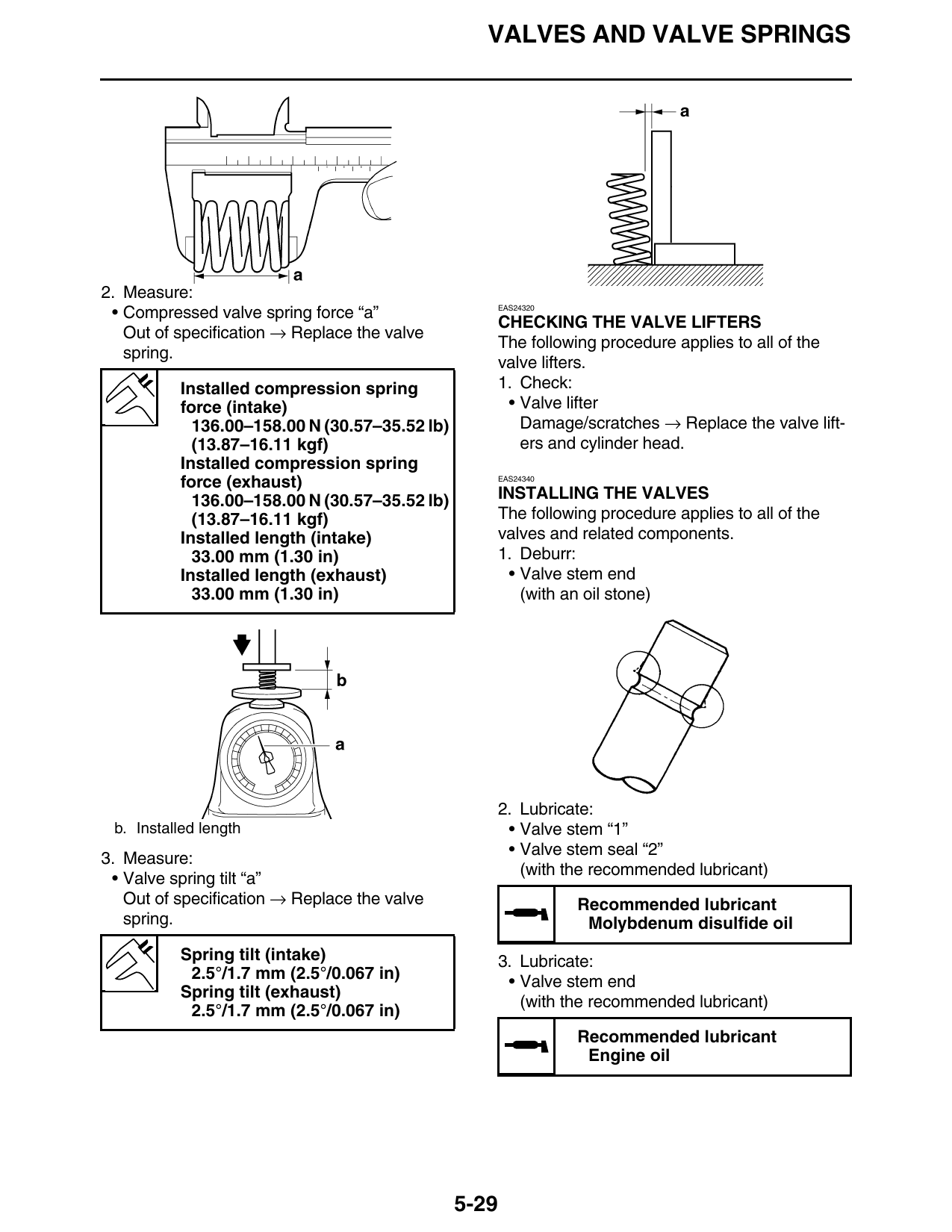
2. Measure:
EAS24320
• Compressed valve spring force “a”
CHECKING THE VALVE LIFTERS
Out of specification → Replace the valve
The following procedure applies to all of the
spring.
valve lifters.
Installed compression spring 1. Check:
force (intake) • Valve lifter
136.00–158.00 N (30.57–35.52 lb) Damage/scratches → Replace the valve lift-
(13.87–16.11 kgf) ers and cylinder head.
Installed compression spring
force (exhaust) EAS24340
136.00–158.00 N (30.57–35.52 lb) INSTALLING THE VALVES
(13.87–16.11 kgf) The following procedure applies to all of the
Installed length (intake) valves and related components.
33.00 mm (1.30 in) 1. Deburr:
Installed length (exhaust) • Valve stem end
33.00 mm (1.30 in) (with an oil stone)
2. Lubricate:
b. Installed length • Valve stem “1”
• Valve stem seal “2”
3. Measure:
(with the recommended lubricant)
• Valve spring tilt “a”
Out of specification → Replace the valve Recommended lubricant
spring. Molybdenum disulfide oil
Spring tilt (intake) 3. Lubricate:
2.5°/1.7 mm (2.5°/0.067 in) • Valve stem end
Spring tilt (exhaust)
(with the recommended lubricant)
2.5°/1.7 mm (2.5°/0.067 in)
Recommended lubricant
Engine oil
5-29
VALVES AND VALVE SPRINGS
Valve spring compressor
90890-04019
YM-04019
Valve spring compressor attach-
ment
90890-04114
Valve spring compressor adapt-
er 19.5 mm
YM-04114
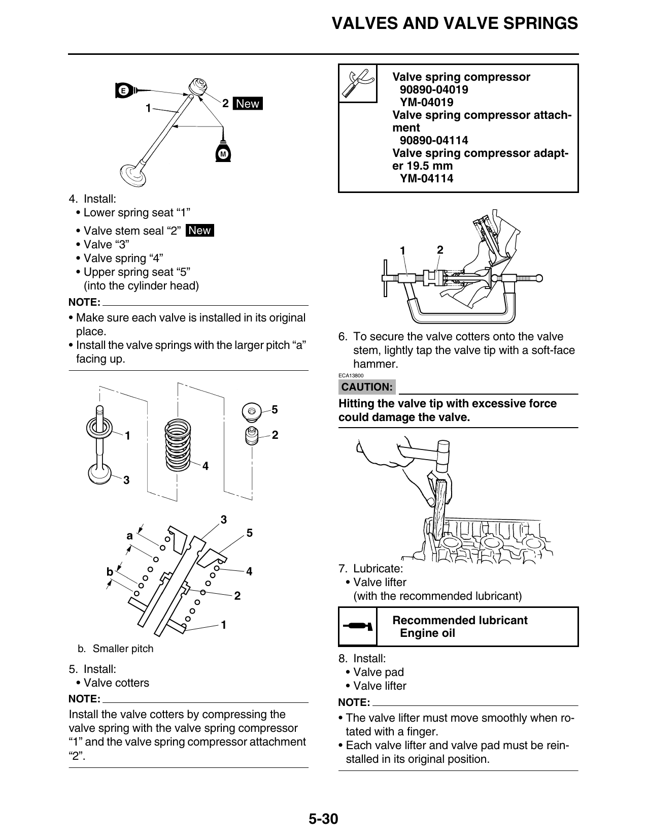
4. Install:
• Lower spring seat “1”
• Valve stem seal “2” New
• Valve “3”
• Valve spring “4”
• Upper spring seat “5”
(into the cylinder head)
NOTE:
• Make sure each valve is installed in its original
place. 6. To secure the valve cotters onto the valve
• Install the valve springs with the larger pitch “a” stem, lightly tap the valve tip with a soft-face
facing up. hammer.
ECA13800
CAUTION:
Hitting the valve tip with excessive force
could damage the valve.
7. Lubricate:
• Valve lifter
(with the recommended lubricant)
Recommended lubricant
Engine oil
b. Smaller pitch
8. Install:
5. Install: • Valve pad
• Valve cotters • Valve lifter
NOTE: NOTE:
Install the valve cotters by compressing the • The valve lifter must move smoothly when ro-
valve spring with the valve spring compressor tated with a finger.
“1” and the valve spring compressor attachment • Each valve lifter and valve pad must be rein-
“2”. stalled in its original position.
5-30