Removing The Clutch
Fragment manuala — str. 357
📋 Tekst do skopiowania / wyszukiwania
CLUTCH
EAS25080
REMOVING THE CLUTCH NOTE:
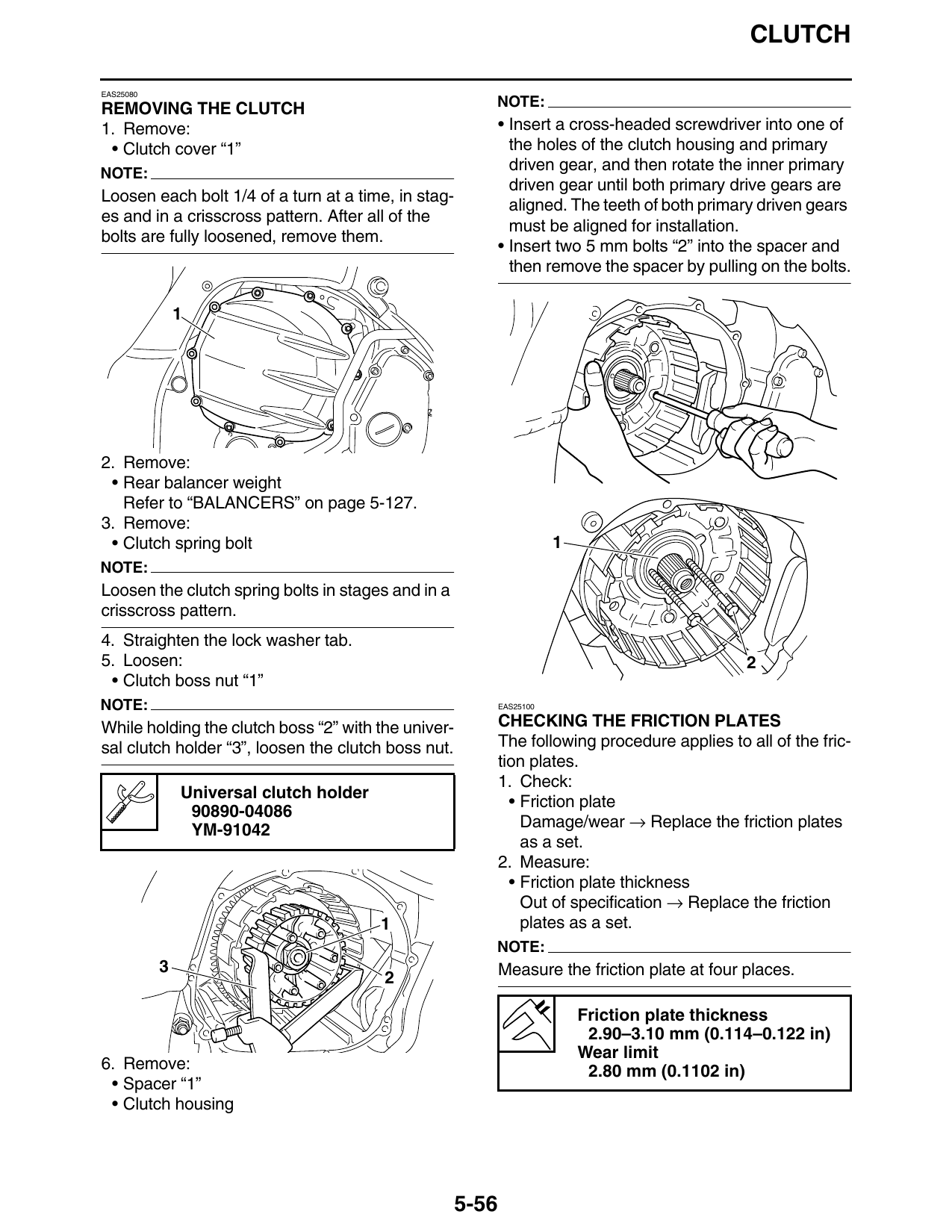
1. Remove: • Insert a cross-headed screwdriver into one of
• Clutch cover “1” the holes of the clutch housing and primary
NOTE:
driven gear, and then rotate the inner primary
driven gear until both primary drive gears are
Loosen each bolt 1/4 of a turn at a time, in stag-
aligned. The teeth of both primary driven gears
es and in a crisscross pattern. After all of the
must be aligned for installation.
bolts are fully loosened, remove them.
• Insert two 5 mm bolts “2” into the spacer and
then remove the spacer by pulling on the bolts.
2. Remove:
• Rear balancer weight
Refer to “BALANCERS” on page 5-127.
3. Remove:
• Clutch spring bolt 1
NOTE:
Loosen the clutch spring bolts in stages and in a
crisscross pattern.
4. Straighten the lock washer tab.
5. Loosen: 2
• Clutch boss nut “1”
NOTE: EAS25100
While holding the clutch boss “2” with the univer- CHECKING THE FRICTION PLATES
sal clutch holder “3”, loosen the clutch boss nut. The following procedure applies to all of the fric-
tion plates.
1. Check:
Universal clutch holder
• Friction plate
90890-04086
YM-91042 Damage/wear → Replace the friction plates
as a set.
2. Measure:
• Friction plate thickness
Out of specification → Replace the friction
1 plates as a set.
NOTE:
3 Measure the friction plate at four places.
Friction plate thickness
2.90–3.10 mm (0.114–0.122 in)
Wear limit
6. Remove: 2.80 mm (0.1102 in)
• Spacer “1”
• Clutch housing
5-56