Installing The Water Pump
Fragment manuala — str. 448–450
📋 Tekst do skopiowania / wyszukiwania
WATER PUMP
Mechanical seal installer Impeller shaft tilt limit
90890-04078 0.15 mm (0.006 in)
Water pump seal installer
YM-33221-A
Middle driven shaft bearing driv-
er
90890-04058
Bearing driver 40 mm
YM-04058
Yamaha bond No. 1215
90890-85505
(Three Bond No.1215®)
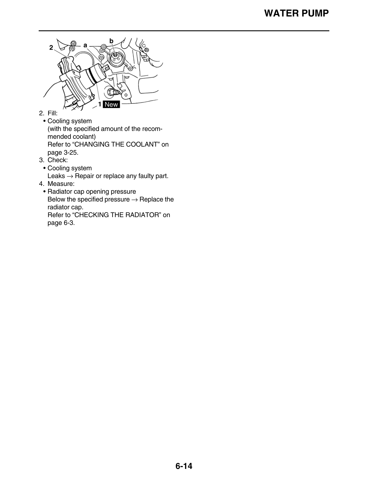
1. Straightedge
2. Impeller
5. Install:
• Impeller “1”
• Circlip New
NOTE:
After installation, check that the impeller shaft ro-
tates smoothly.
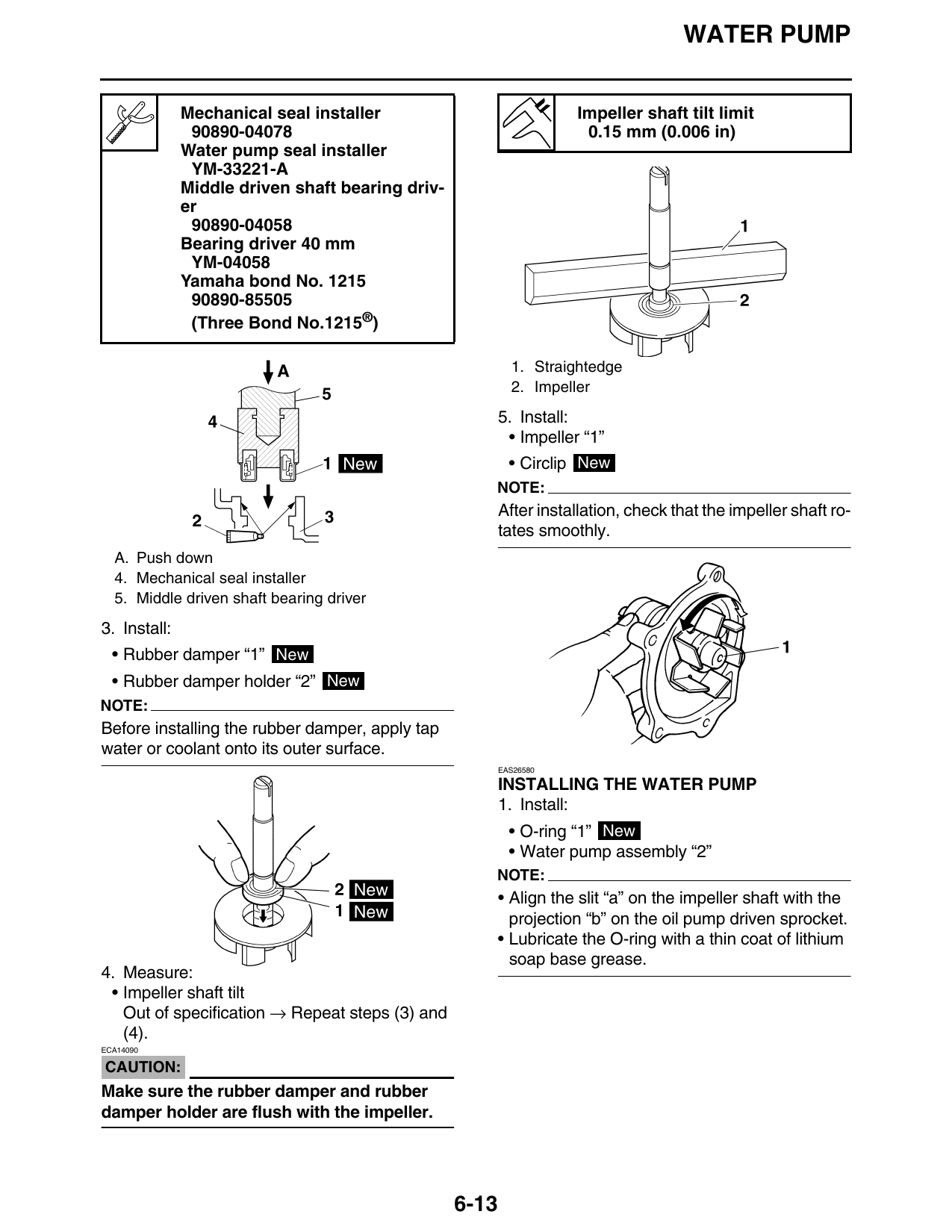
A. Push down
4. Mechanical seal installer
5. Middle driven shaft bearing driver
3. Install:
• Rubber damper “1” New
• Rubber damper holder “2” New
NOTE:
Before installing the rubber damper, apply tap
water or coolant onto its outer surface.
EAS26580
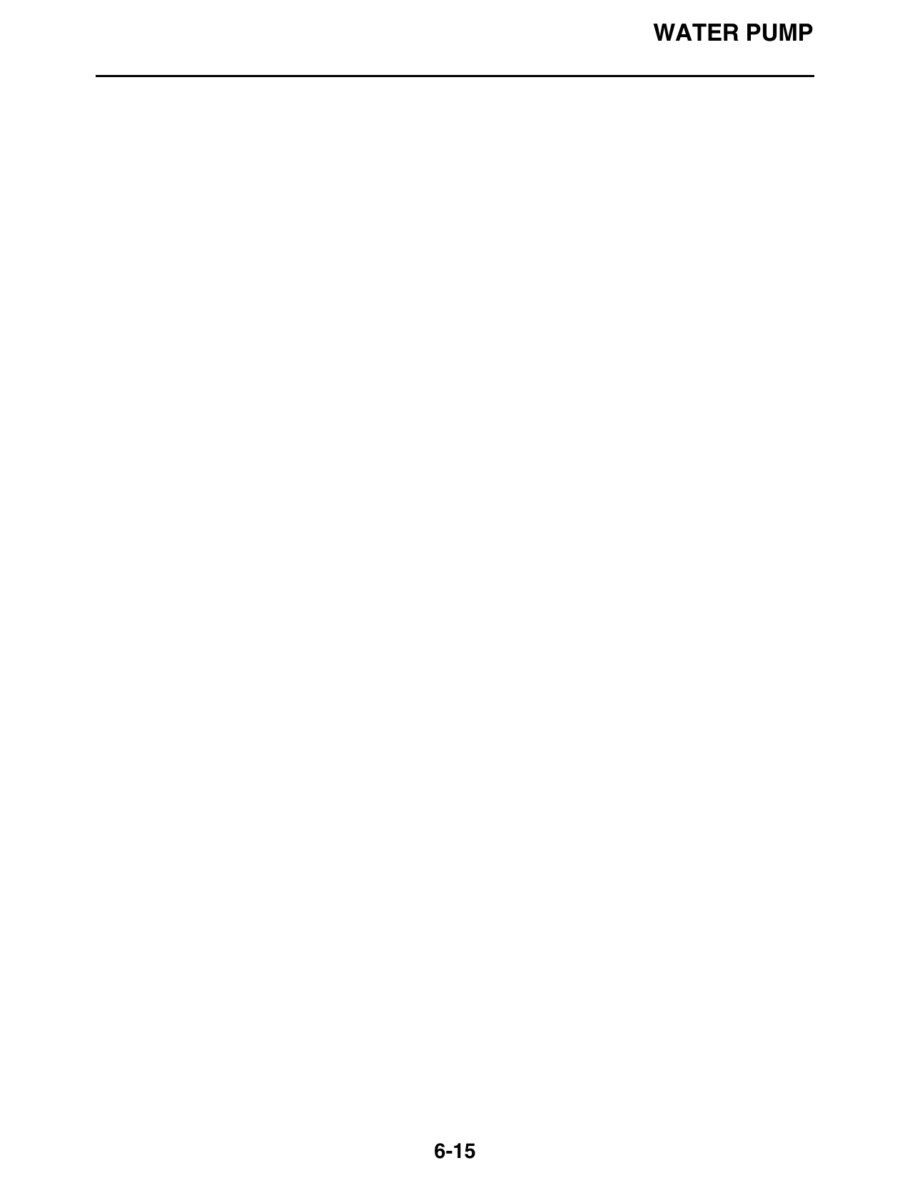
INSTALLING THE WATER PUMP
1. Install:
• O-ring “1” New
• Water pump assembly “2”
NOTE:
• Align the slit “a” on the impeller shaft with the
projection “b” on the oil pump driven sprocket.
• Lubricate the O-ring with a thin coat of lithium
soap base grease.
4. Measure:
• Impeller shaft tilt
Out of specification → Repeat steps (3) and
(4).
ECA14090
CAUTION:
Make sure the rubber damper and rubber
damper holder are flush with the impeller.
6-13
WATER PUMP
2. Fill:
• Cooling system
(with the specified amount of the recom-
mended coolant)
Refer to “CHANGING THE COOLANT” on
page 3-25.
3. Check:
• Cooling system
Leaks → Repair or replace any faulty part.
4. Measure:
• Radiator cap opening pressure
Below the specified pressure → Replace the
radiator cap.
Refer to “CHECKING THE RADIATOR” on
page 6-3.
6-14
WATER PUMP
6-15