[C-7] Diagnosis By The Malfunction Code
Fragment manuala — str. 613–625
📋 Tekst do skopiowania / wyszukiwania
ABS (ANTI-LOCK BRAKE SYSTEM)
EAS27880
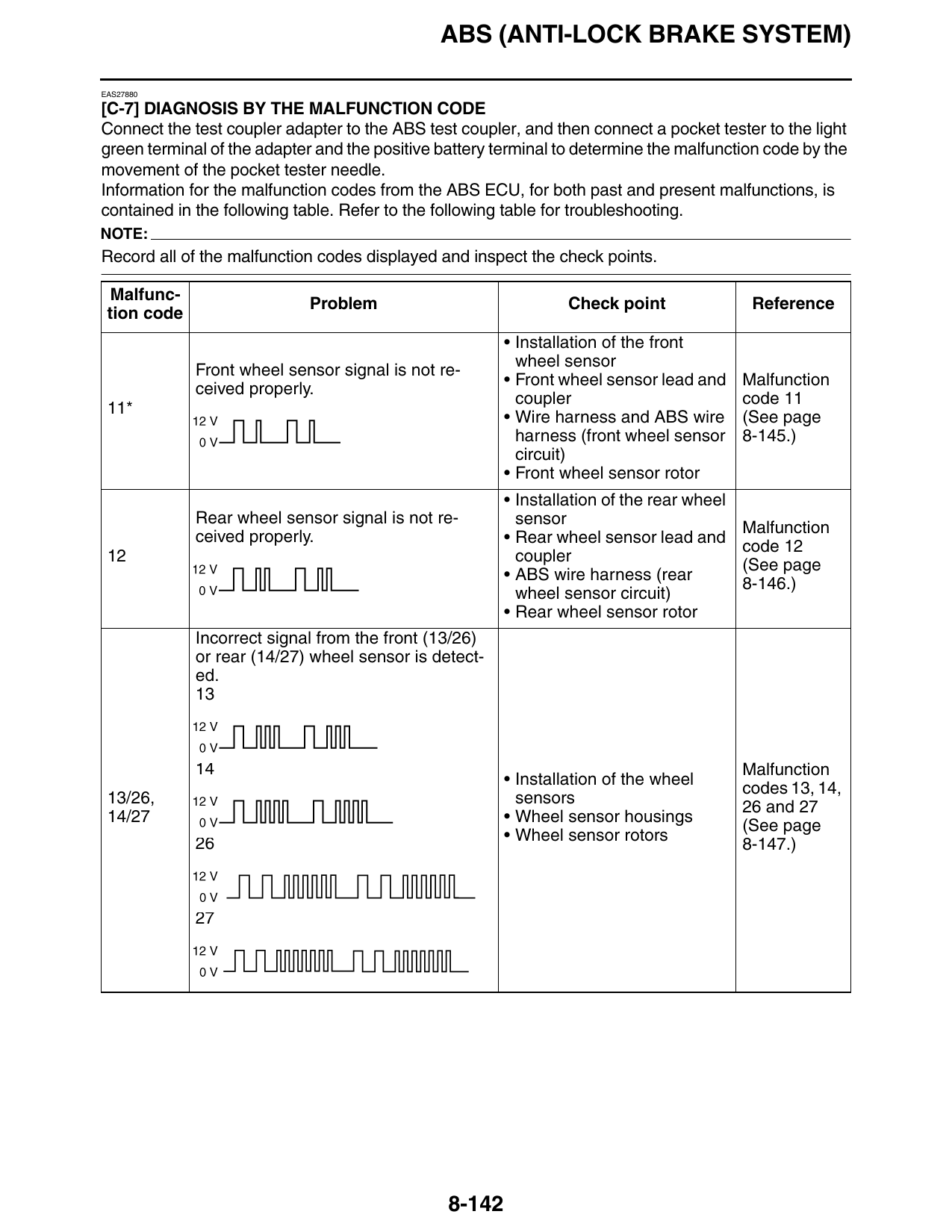
[C-7] DIAGNOSIS BY THE MALFUNCTION CODE
Connect the test coupler adapter to the ABS test coupler, and then connect a pocket tester to the light
green terminal of the adapter and the positive battery terminal to determine the malfunction code by the
movement of the pocket tester needle.
Information for the malfunction codes from the ABS ECU, for both past and present malfunctions, is
contained in the following table. Refer to the following table for troubleshooting.
NOTE:
Record all of the malfunction codes displayed and inspect the check points.
Malfunc-
Problem Check point Reference
tion code
• Installation of the front
wheel sensor
Front wheel sensor signal is not re-
• Front wheel sensor lead and Malfunction
ceived properly.
coupler code 11
11*
• Wire harness and ABS wire (See page
harness (front wheel sensor 8-145.)
circuit)
• Front wheel sensor rotor
• Installation of the rear wheel
Rear wheel sensor signal is not re- sensor
ceived properly. Malfunction
• Rear wheel sensor lead and
code 12
12 coupler
(See page
• ABS wire harness (rear
8-146.)
wheel sensor circuit)
• Rear wheel sensor rotor
Incorrect signal from the front (13/26)
or rear (14/27) wheel sensor is detect-
ed.
14 Malfunction
• Installation of the wheel
codes 13, 14,
13/26, sensors
26 and 27
14/27 • Wheel sensor housings
(See page
26 • Wheel sensor rotors
8-147.)
8-142
ABS (ANTI-LOCK BRAKE SYSTEM)
Malfunc-
Problem Check point Reference
tion code
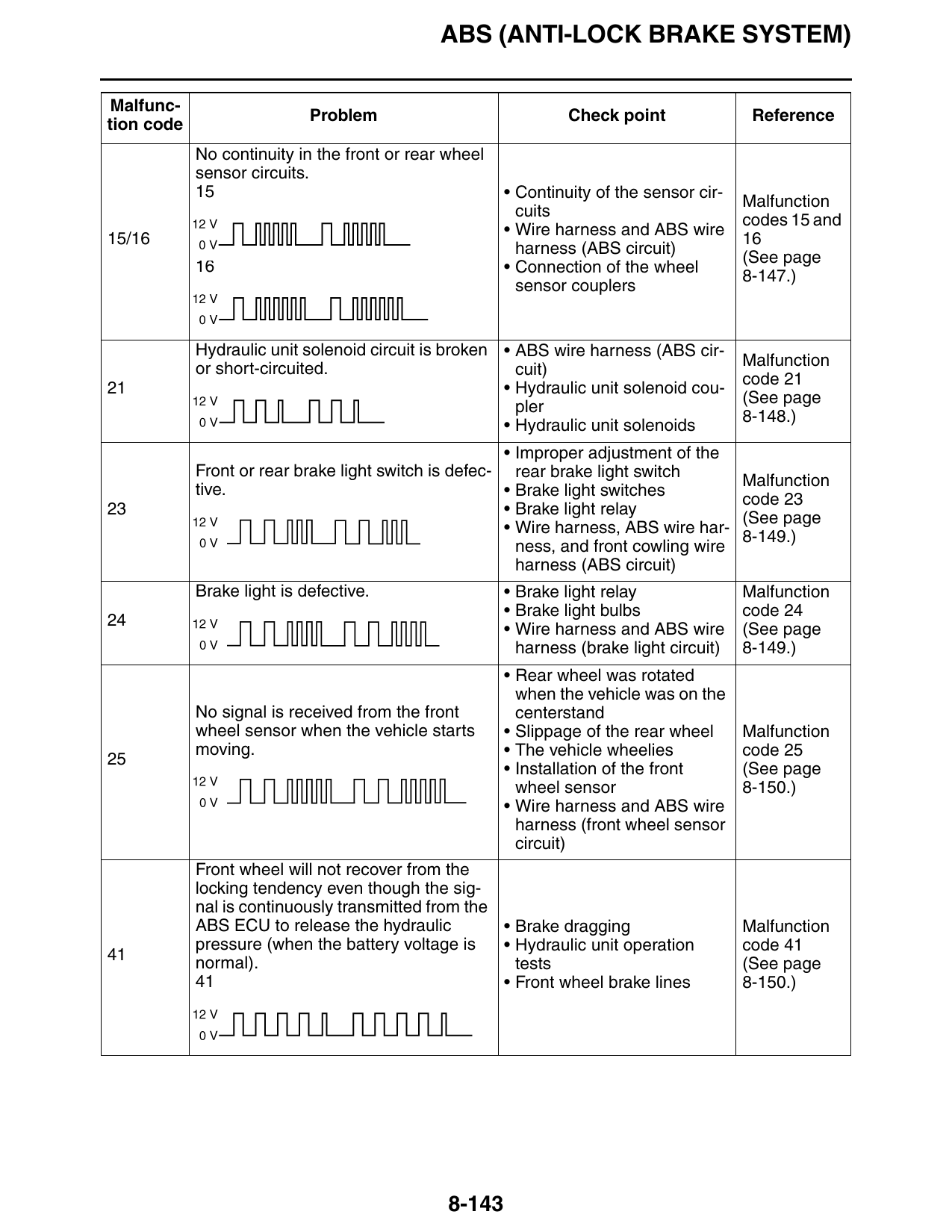
No continuity in the front or rear wheel
sensor circuits.
15 • Continuity of the sensor cir-
Malfunction
cuits
codes 15 and
• Wire harness and ABS wire
15/16 16
harness (ABS circuit)
(See page
16 • Connection of the wheel
8-147.)
sensor couplers
Hydraulic unit solenoid circuit is broken • ABS wire harness (ABS cir-
Malfunction
or short-circuited. cuit)
code 21
21 • Hydraulic unit solenoid cou-
(See page
pler
8-148.)
• Hydraulic unit solenoids
• Improper adjustment of the
Front or rear brake light switch is defec- rear brake light switch
Malfunction
tive. • Brake light switches
code 23
23 • Brake light relay
(See page
• Wire harness, ABS wire har-
8-149.)
ness, and front cowling wire
harness (ABS circuit)
Brake light is defective. • Brake light relay Malfunction
• Brake light bulbs code 24
• Wire harness and ABS wire (See page
harness (brake light circuit) 8-149.)
• Rear wheel was rotated
when the vehicle was on the
No signal is received from the front centerstand
wheel sensor when the vehicle starts • Slippage of the rear wheel Malfunction
moving. • The vehicle wheelies code 25
• Installation of the front (See page
wheel sensor 8-150.)
• Wire harness and ABS wire
harness (front wheel sensor
circuit)
Front wheel will not recover from the
locking tendency even though the sig-
nal is continuously transmitted from the
ABS ECU to release the hydraulic • Brake dragging Malfunction
pressure (when the battery voltage is • Hydraulic unit operation code 41
normal). tests (See page
41 • Front wheel brake lines 8-150.)
8-143
ABS (ANTI-LOCK BRAKE SYSTEM)
Malfunc-
Problem Check point Reference
tion code
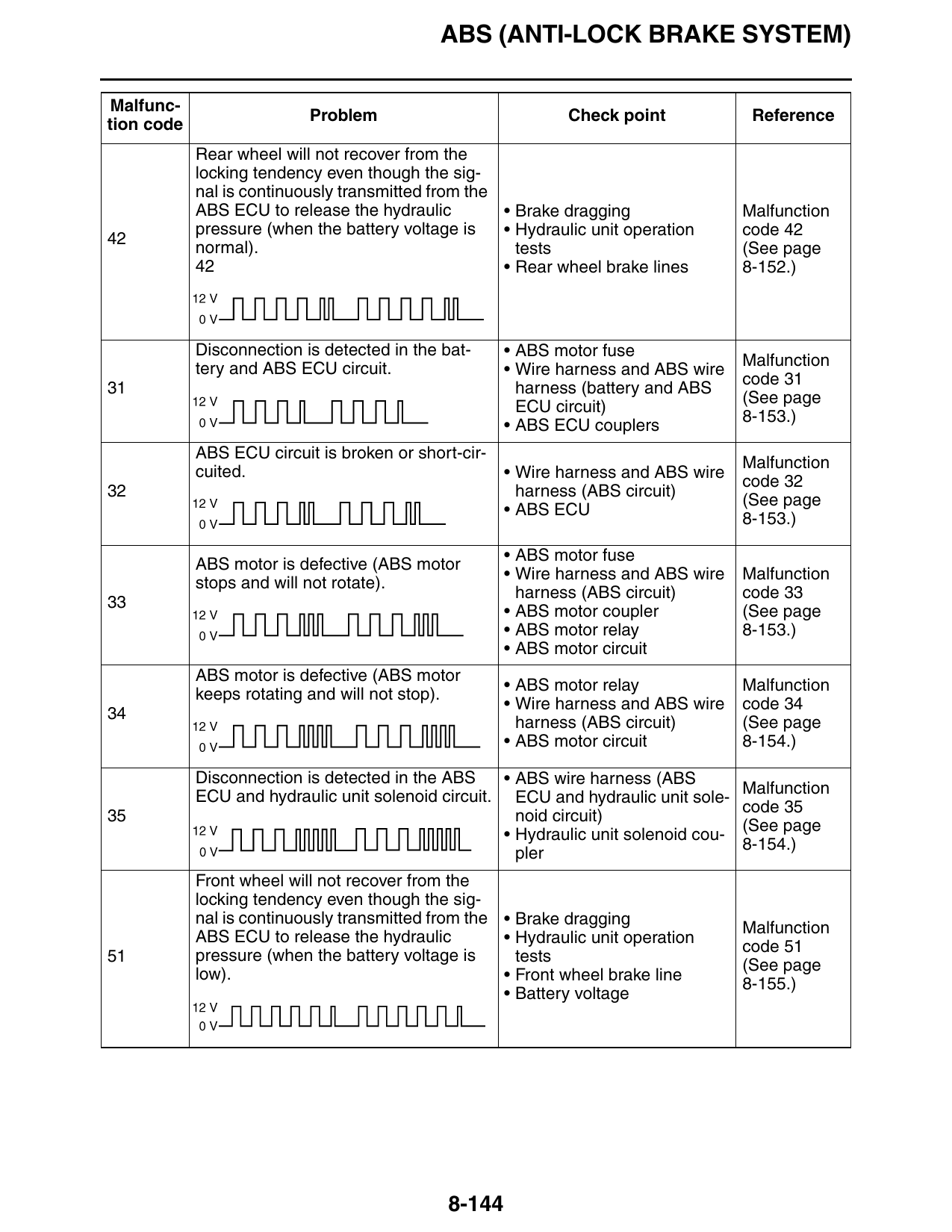
Rear wheel will not recover from the
locking tendency even though the sig-
nal is continuously transmitted from the
ABS ECU to release the hydraulic • Brake dragging Malfunction
pressure (when the battery voltage is • Hydraulic unit operation code 42
normal). tests (See page
42 • Rear wheel brake lines 8-152.)
Disconnection is detected in the bat- • ABS motor fuse
Malfunction
tery and ABS ECU circuit. • Wire harness and ABS wire
code 31
31 harness (battery and ABS
(See page
ECU circuit)
8-153.)
• ABS ECU couplers
ABS ECU circuit is broken or short-cir-
Malfunction
cuited. • Wire harness and ABS wire
code 32
32 harness (ABS circuit)
(See page
• ABS ECU
8-153.)
• ABS motor fuse
ABS motor is defective (ABS motor
• Wire harness and ABS wire Malfunction
stops and will not rotate).
harness (ABS circuit) code 33
• ABS motor coupler (See page
• ABS motor relay 8-153.)
• ABS motor circuit
ABS motor is defective (ABS motor
• ABS motor relay Malfunction
keeps rotating and will not stop).
• Wire harness and ABS wire code 34
harness (ABS circuit) (See page
• ABS motor circuit 8-154.)
Disconnection is detected in the ABS • ABS wire harness (ABS
Malfunction
ECU and hydraulic unit solenoid circuit. ECU and hydraulic unit sole-
code 35
35 noid circuit)
(See page
• Hydraulic unit solenoid cou-
8-154.)
pler
Front wheel will not recover from the
locking tendency even though the sig-
nal is continuously transmitted from the • Brake dragging
ABS ECU to release the hydraulic Malfunction
• Hydraulic unit operation
pressure (when the battery voltage is code 51
51 tests
low). (See page
• Front wheel brake line
8-155.)
• Battery voltage
8-144
ABS (ANTI-LOCK BRAKE SYSTEM)
Malfunc-
Problem Check point Reference
tion code
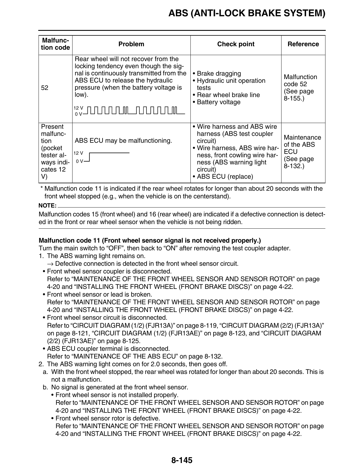
Rear wheel will not recover from the
locking tendency even though the sig-
nal is continuously transmitted from the • Brake dragging
Malfunction
ABS ECU to release the hydraulic • Hydraulic unit operation
code 52
52 pressure (when the battery voltage is tests
(See page
low). • Rear wheel brake line
8-155.)
• Battery voltage
Present • Wire harness and ABS wire
malfunc- harness (ABS test coupler
Maintenance
tion ABS ECU may be malfunctioning. circuit)
of the ABS
(pocket • Wire harness, ABS wire har-
ECU
tester al- ness, front cowling wire har-
(See page
ways indi- ness (ABS warning light
8-132.)
cates 12 circuit)
V) • ABS ECU (replace)
* Malfunction code 11 is indicated if the rear wheel rotates for longer than about 20 seconds with the
front wheel stopped (e.g., when the vehicle is on the centerstand).
NOTE:
Malfunction codes 15 (front wheel) and 16 (rear wheel) are indicated if a defective connection is detect-
ed in the front or rear wheel sensor when the vehicle is not being ridden.
Malfunction code 11 (Front wheel sensor signal is not received properly.)
Turn the main switch to “OFF”, then back to “ON” after removing the test coupler adapter.
1. The ABS warning light remains on.
→ Defective connection is detected in the front wheel sensor circuit.
• Front wheel sensor coupler is disconnected.
Refer to “MAINTENANCE OF THE FRONT WHEEL SENSOR AND SENSOR ROTOR” on page
4-20 and “INSTALLING THE FRONT WHEEL (FRONT BRAKE DISCS)” on page 4-22.
• Front wheel sensor or lead is broken.
Refer to “MAINTENANCE OF THE FRONT WHEEL SENSOR AND SENSOR ROTOR” on page
4-20 and “INSTALLING THE FRONT WHEEL (FRONT BRAKE DISCS)” on page 4-22.
• Front wheel sensor circuit is disconnected.
Refer to “CIRCUIT DIAGRAM (1/2) (FJR13A)” on page 8-119, “CIRCUIT DIAGRAM (2/2) (FJR13A)”
on page 8-121, “CIRCUIT DIAGRAM (1/2) (FJR13AE)” on page 8-123, and “CIRCUIT DIAGRAM
(2/2) (FJR13AE)” on page 8-125.
• ABS ECU coupler terminal is disconnected.
Refer to “MAINTENANCE OF THE ABS ECU” on page 8-132.
2. The ABS warning light comes on for 2.0 seconds, then goes off.
a. With the front wheel stopped, the rear wheel was rotated for longer than about 20 seconds. This is
not a malfunction.
b. No signal is generated at the front wheel sensor.
• Front wheel sensor is not installed properly.
Refer to “MAINTENANCE OF THE FRONT WHEEL SENSOR AND SENSOR ROTOR” on page
4-20 and “INSTALLING THE FRONT WHEEL (FRONT BRAKE DISCS)” on page 4-22.
• Front wheel sensor rotor is defective.
Refer to “MAINTENANCE OF THE FRONT WHEEL SENSOR AND SENSOR ROTOR” on page
4-20 and “INSTALLING THE FRONT WHEEL (FRONT BRAKE DISCS)” on page 4-22.
8-145
ABS (ANTI-LOCK BRAKE SYSTEM)
c. Front wheel sensor circuit is short-circuited.
• Front wheel sensor or lead is short-circuited.
Refer to “MAINTENANCE OF THE FRONT WHEEL SENSOR AND SENSOR ROTOR” on page
4-20 and “INSTALLING THE FRONT WHEEL (FRONT BRAKE DISCS)” on page 4-22.
• ABS wire harness and wire harness are short-circuited.
Refer to “CIRCUIT DIAGRAM (1/2) (FJR13A)” on page 8-119, “CIRCUIT DIAGRAM (2/2)
(FJR13A)” on page 8-121, “CIRCUIT DIAGRAM (1/2) (FJR13AE)” on page 8-123, and “CIRCUIT
DIAGRAM (2/2) (FJR13AE)” on page 8-125.
d. Front wheel sensor output drops.
• Sensor signal output may drop due to failure of the bearings, wheel axle, wheel, or sensor hous-
ing of the front wheel. Check these components, without removing them, for looseness, distor-
tion, and bends.
Malfunction code 12 (Rear wheel sensor signal is not received properly.)
Turn the main switch to “OFF”, then back to “ON”.
1. The ABS warning light remains on.
→ Defective connection is detected in the rear wheel sensor circuit.
• Rear wheel sensor coupler is disconnected.
Refer to “MAINTENANCE OF THE REAR WHEEL SENSOR AND SENSOR ROTOR” on page 4-26
and “INSTALLING THE REAR WHEEL (REAR BRAKE DISC)” on page 4-27.
• Rear wheel sensor or lead is broken.
Refer to “MAINTENANCE OF THE REAR WHEEL SENSOR AND SENSOR ROTOR” on page 4-26
and “INSTALLING THE REAR WHEEL (REAR BRAKE DISC)” on page 4-27.
• Rear wheel sensor circuit is disconnected.
Refer to “CIRCUIT DIAGRAM (1/2) (FJR13A)” on page 8-119, “CIRCUIT DIAGRAM (2/2) (FJR13A)”
on page 8-121, “CIRCUIT DIAGRAM (1/2) (FJR13AE)” on page 8-123, and “CIRCUIT DIAGRAM
(2/2) (FJR13AE)” on page 8-125.
• ABS ECU coupler terminal is disconnected.
Refer to “MAINTENANCE OF THE ABS ECU” on page 8-132.
2. The ABS warning light comes on for 2.0 seconds, then goes off.
a. With the rear wheel stopped, the front wheel was rotated at a speed faster than about 11 km/h.
This is not a malfunction.
b. No signal is generated at the rear wheel sensor.
• Rear wheel sensor is not installed properly.
Refer to “MAINTENANCE OF THE REAR WHEEL SENSOR AND SENSOR ROTOR” on page
4-26 and “INSTALLING THE REAR WHEEL (REAR BRAKE DISC)” on page 4-27.
• Rear wheel sensor rotor is defective.
Refer to “MAINTENANCE OF THE REAR WHEEL SENSOR AND SENSOR ROTOR” on page
4-26 and “INSTALLING THE REAR WHEEL (REAR BRAKE DISC)” on page 4-27.
c. Rear wheel sensor circuit is short-circuited.
• Rear wheel sensor or lead is short-circuited.
Refer to “MAINTENANCE OF THE REAR WHEEL SENSOR AND SENSOR ROTOR” on page
4-26 and “INSTALLING THE REAR WHEEL (REAR BRAKE DISC)” on page 4-27.
• ABS wire harness is short-circuited.
Refer to “CIRCUIT DIAGRAM (1/2) (FJR13A)” on page 8-119, “CIRCUIT DIAGRAM (2/2)
(FJR13A)” on page 8-121, “CIRCUIT DIAGRAM (1/2) (FJR13AE)” on page 8-123, and “CIRCUIT
DIAGRAM (2/2) (FJR13AE)” on page 8-125.
d. Rear wheel sensor output drops.
• Sensor signal output may drop due to failure of the bearings, wheel axle, wheel, or sensor hous-
ing of the rear wheel. Check these components, without removing them, for looseness, distortion,
and bends.
8-146
ABS (ANTI-LOCK BRAKE SYSTEM)
NOTE:
If the vehicle is continuously ridden on extremely uneven roads, the ABS warning light may flash and
malfunction code 11 or 12 may be recorded depending on the condition.
Malfunction codes 13/26 (front wheel) and 14/27 (rear wheel) (Incorrect signal from the front
(13/26) or rear (14/27) wheel sensor is detected.)
1. The wheel sensors or sensor rotors are not properly installed.
a. Installation of the front or rear wheel sensor
• Check that the wheel sensor is properly installed in the housing.
Refer to “MAINTENANCE OF THE FRONT WHEEL SENSOR AND SENSOR ROTOR” on page
4-20, “INSTALLING THE FRONT WHEEL (FRONT BRAKE DISCS)” on page 4-22, “MAINTE-
NANCE OF THE REAR WHEEL SENSOR AND SENSOR ROTOR” on page 4-26, and “IN-
STALLING THE REAR WHEEL (REAR BRAKE DISC)” on page 4-27.
• Check if there is looseness between the housing and wheel.
Refer to “MAINTENANCE OF THE FRONT WHEEL SENSOR AND SENSOR ROTOR” on page
4-20, “INSTALLING THE FRONT WHEEL (FRONT BRAKE DISCS)” on page 4-22, “MAINTE-
NANCE OF THE REAR WHEEL SENSOR AND SENSOR ROTOR” on page 4-26, and “IN-
STALLING THE REAR WHEEL (REAR BRAKE DISC)” on page 4-27.
b. Installation of the front or rear wheel sensor rotor
• Check that the sensor rotor is correctly pressed in the wheel.
Refer to “MAINTENANCE OF THE FRONT WHEEL SENSOR AND SENSOR ROTOR” on page
4-20, “INSTALLING THE FRONT WHEEL (FRONT BRAKE DISCS)” on page 4-22, “MAINTE-
NANCE OF THE REAR WHEEL SENSOR AND SENSOR ROTOR” on page 4-26, and “IN-
STALLING THE REAR WHEEL (REAR BRAKE DISC)” on page 4-27.
• Check the rotor and inside the rotor housing for foreign materials.
Refer to “MAINTENANCE OF THE FRONT WHEEL SENSOR AND SENSOR ROTOR” on page
4-20, “INSTALLING THE FRONT WHEEL (FRONT BRAKE DISCS)” on page 4-22, “MAINTE-
NANCE OF THE REAR WHEEL SENSOR AND SENSOR ROTOR” on page 4-26, and “IN-
STALLING THE REAR WHEEL (REAR BRAKE DISC)” on page 4-27.
2. Teeth surfaces of the sensor rotors are defective.
• Check if there are flaws on the surfaces of the sensor rotor teeth. Also, check for any foreign mate-
rials.
Refer to “MAINTENANCE OF THE FRONT WHEEL SENSOR AND SENSOR ROTOR” on page
4-20, “INSTALLING THE FRONT WHEEL (FRONT BRAKE DISCS)” on page 4-22, “MAINTE-
NANCE OF THE REAR WHEEL SENSOR AND SENSOR ROTOR” on page 4-26, and “INSTALL-
ING THE REAR WHEEL (REAR BRAKE DISC)” on page 4-27.
3. Sensor output has dropped.
• Sensor signal output may drop due to failure of the bearings, wheel axle, wheel, or sensor housing
of the front or rear wheel. Check these components, without removing them, for looseness, distor-
tion, and bends.
Malfunction codes 15 (front wheel) and 16 (rear wheel) (No continuity in the front or rear wheel
sensor circuit.)
Broken front or rear wheel sensor circuit is detected.
• Front or rear wheel sensor coupler is disconnected.
Refer to “MAINTENANCE OF THE FRONT WHEEL SENSOR AND SENSOR ROTOR” on page
4-20, “INSTALLING THE FRONT WHEEL (FRONT BRAKE DISCS)” on page 4-22, “MAINTENANCE
OF THE REAR WHEEL SENSOR AND SENSOR ROTOR” on page 4-26, and “INSTALLING THE
REAR WHEEL (REAR BRAKE DISC)” on page 4-27.
8-147
ABS (ANTI-LOCK BRAKE SYSTEM)
• Front or rear wheel sensor or lead is broken.
Refer to “MAINTENANCE OF THE FRONT WHEEL SENSOR AND SENSOR ROTOR” on page
4-20, “INSTALLING THE FRONT WHEEL (FRONT BRAKE DISCS)” on page 4-22, “MAINTENANCE
OF THE REAR WHEEL SENSOR AND SENSOR ROTOR” on page 4-26, and “INSTALLING THE
REAR WHEEL (REAR BRAKE DISC)” on page 4-27.
• Front or rear wheel sensor circuit is broken.
Refer to “CIRCUIT DIAGRAM (1/2) (FJR13A)” on page 8-119, “CIRCUIT DIAGRAM (2/2) (FJR13A)”
on page 8-121, “CIRCUIT DIAGRAM (1/2) (FJR13AE)” on page 8-123, and “CIRCUIT DIAGRAM
(2/2) (FJR13AE)” on page 8-125.
• ABS wire harness is disconnected from the ABS ECU coupler terminal.
Refer to “MAINTENANCE OF THE ABS ECU” on page 8-132.
NOTE:
• Check that both the front and rear wheel sensor couplers are connected securely.
• If the vehicle is ridden after malfunction code 15 (front wheel) or 16 (rear wheel) is displayed, the mal-
function code will be overwritten from 15 to 11 (front wheel) or from 16 to 12 (rear wheel).
Malfunction code 21 (Hydraulic unit solenoid circuit is broken or short-circuited.)
1. Hydraulic unit solenoid coupler
• Check if a hydraulic unit solenoid coupler terminal is disconnected.
Refer to “ABS COUPLER LOCATION CHART” on page 8-129.
2. Hydraulic unit solenoids
• Check the solenoids (front brake, rear brake, and unified brake system) for continuity.
Refer to “MAINTENANCE OF THE HYDRAULIC UNIT” on page 8-132.
• Check the insulation between each solenoid terminal and the negative battery terminal.
Refer to “MAINTENANCE OF THE HYDRAULIC UNIT” on page 8-132.
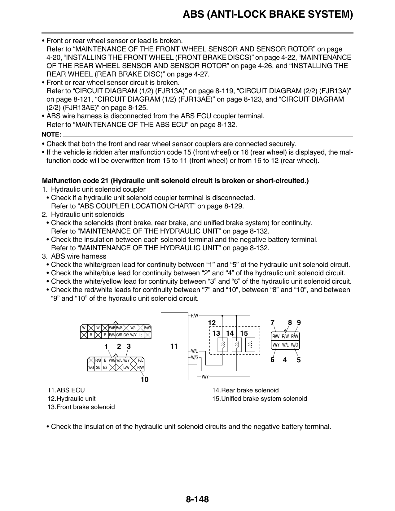
3. ABS wire harness
• Check the white/green lead for continuity between “1” and “5” of the hydraulic unit solenoid circuit.
• Check the white/blue lead for continuity between “2” and “4” of the hydraulic unit solenoid circuit.
• Check the white/yellow lead for continuity between “3” and “6” of the hydraulic unit solenoid circuit.
• Check the red/white leads for continuity between “7” and “10”, between “8” and “10”, and between
“9” and “10” of the hydraulic unit solenoid circuit.
R/W
12 7 8 9
W W W/B Br/B W/L Br/W
B B B/W G/R G/Y W/Y Lg 13 14 15 R/W R/W R/W
1 2 3 11 W/Y W/L W/G
W/L
W/G
R/B B W/G W/L W/Y R/L 6 4 5
Y/G Sb B2 L/W R/W
W/Y
11.ABS ECU 14.Rear brake solenoid
12.Hydraulic unit 15.Unified brake system solenoid
13.Front brake solenoid
• Check the insulation of the hydraulic unit solenoid circuits and the negative battery terminal.
8-148
ABS (ANTI-LOCK BRAKE SYSTEM)
Malfunction code 23 (Front or rear brake light switch is defective.)
1. Wire harness, ABS wire harness, and front cowling wire harness
• Check the entire anti-lock brake system wiring.
Refer to “CIRCUIT DIAGRAM (1/2) (FJR13A)” on page 8-119, “CIRCUIT DIAGRAM (2/2) (FJR13A)”
on page 8-121, “CIRCUIT DIAGRAM (1/2) (FJR13AE)” on page 8-123, and “CIRCUIT DIAGRAM
(2/2) (FJR13AE)” on page 8-125.
2. Brake light relay
• Check the brake light relay.
Refer to “CHECKING THE RELAYS” on page 8-221.
3. Brake light switches (front and rear)
• Check the brake light switches (front and rear).
Refer to “CHECKING THE SWITCHES” on page 8-211.
4. Rear brake light switch
• Check that the rear brake light switch is adjusted properly.
Refer to “ADJUSTING THE REAR BRAKE LIGHT SWITCH” on page 3-30.
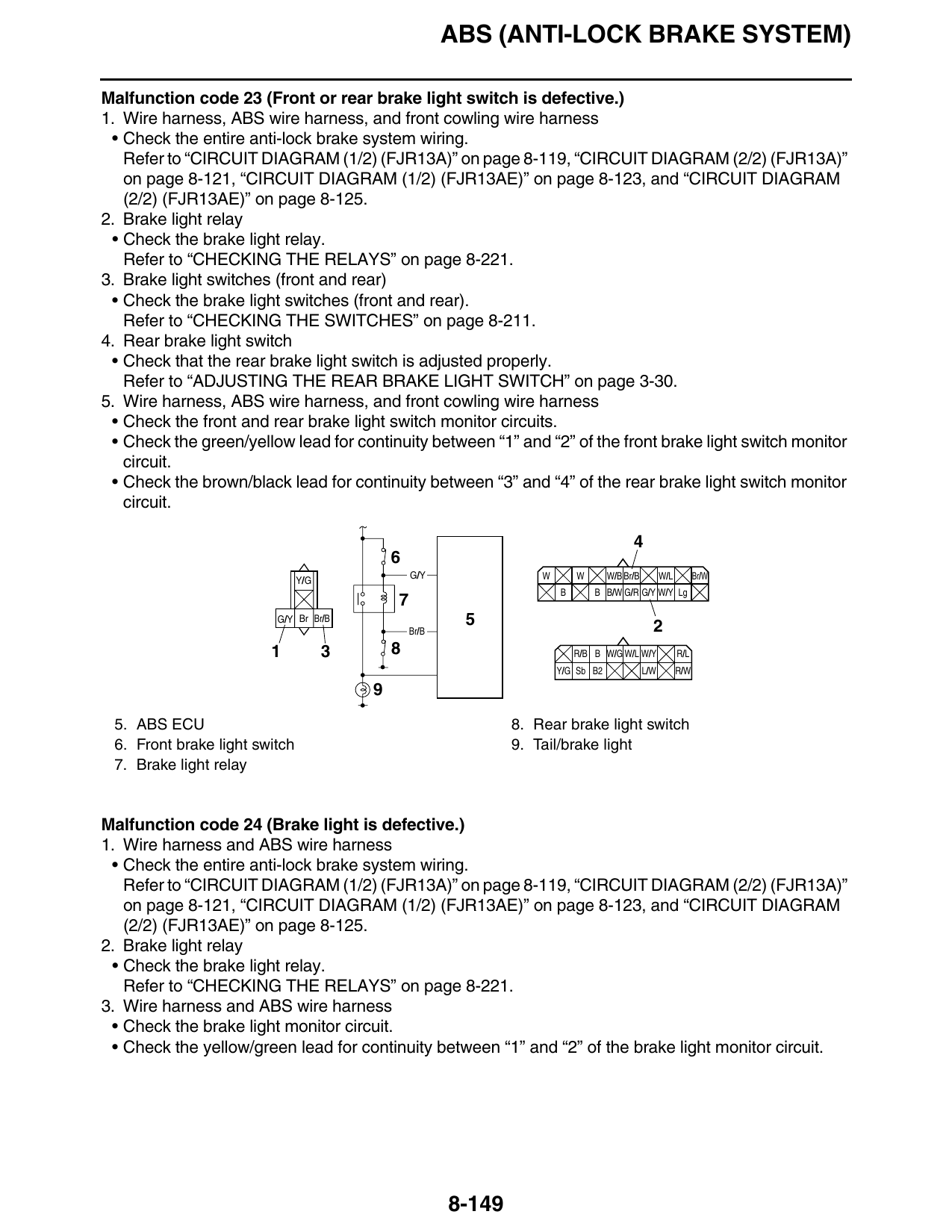
5. Wire harness, ABS wire harness, and front cowling wire harness
• Check the front and rear brake light switch monitor circuits.
• Check the green/yellow lead for continuity between “1” and “2” of the front brake light switch monitor
circuit.
• Check the brown/black lead for continuity between “3” and “4” of the rear brake light switch monitor
circuit.
G/Y W W W/B Br/B W/L Br/W
Y/G
B B B/W G/R G/Y W/Y Lg
G/Y Br Br/B 5 2
Br/B
1 3 8 R/B B W/G W/L W/Y R/L
Y/G Sb B2 L/W R/W
5. ABS ECU 8. Rear brake light switch
6. Front brake light switch 9. Tail/brake light
7. Brake light relay
Malfunction code 24 (Brake light is defective.)
1. Wire harness and ABS wire harness
• Check the entire anti-lock brake system wiring.
Refer to “CIRCUIT DIAGRAM (1/2) (FJR13A)” on page 8-119, “CIRCUIT DIAGRAM (2/2) (FJR13A)”
on page 8-121, “CIRCUIT DIAGRAM (1/2) (FJR13AE)” on page 8-123, and “CIRCUIT DIAGRAM
(2/2) (FJR13AE)” on page 8-125.
2. Brake light relay
• Check the brake light relay.
Refer to “CHECKING THE RELAYS” on page 8-221.
3. Wire harness and ABS wire harness
• Check the brake light monitor circuit.
• Check the yellow/green lead for continuity between “1” and “2” of the brake light monitor circuit.
8-149
ABS (ANTI-LOCK BRAKE SYSTEM)
1 4
W W W/B Br/B W/L Br/W
Y/G
B B B/W G/R G/Y W/Y Lg
G/Y Br Br/B 3
R/B B W/G W/L W/Y R/L
Y/G Sb B2 L/W R/W
Y/G
7 2
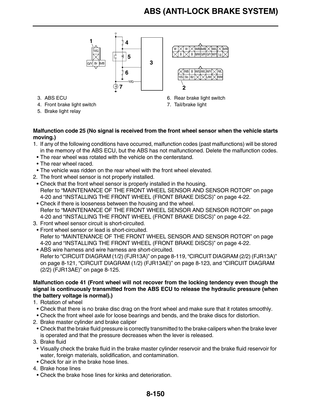
3. ABS ECU 6. Rear brake light switch
4. Front brake light switch 7. Tail/brake light
5. Brake light relay
Malfunction code 25 (No signal is received from the front wheel sensor when the vehicle starts
moving.)
1. If any of the following conditions have occurred, malfunction codes (past malfunctions) will be stored
in the memory of the ABS ECU, but the ABS has not malfunctioned. Delete the malfunction codes.
• The rear wheel was rotated with the vehicle on the centerstand.
• The rear wheel raced.
• The vehicle was ridden on the rear wheel with the front wheel elevated.
2. The front wheel sensor is not properly installed.
• Check that the front wheel sensor is properly installed in the housing.
Refer to “MAINTENANCE OF THE FRONT WHEEL SENSOR AND SENSOR ROTOR” on page
4-20 and “INSTALLING THE FRONT WHEEL (FRONT BRAKE DISCS)” on page 4-22.
• Check if there is looseness between the housing and the wheel.
Refer to “MAINTENANCE OF THE FRONT WHEEL SENSOR AND SENSOR ROTOR” on page
4-20 and “INSTALLING THE FRONT WHEEL (FRONT BRAKE DISCS)” on page 4-22.
3. Front wheel sensor circuit is short-circuited.
• Front wheel sensor or lead is short-circuited.
Refer to “MAINTENANCE OF THE FRONT WHEEL SENSOR AND SENSOR ROTOR” on page
4-20 and “INSTALLING THE FRONT WHEEL (FRONT BRAKE DISCS)” on page 4-22.
• ABS wire harness and wire harness are short-circuited.
Refer to “CIRCUIT DIAGRAM (1/2) (FJR13A)” on page 8-119, “CIRCUIT DIAGRAM (2/2) (FJR13A)”
on page 8-121, “CIRCUIT DIAGRAM (1/2) (FJR13AE)” on page 8-123, and “CIRCUIT DIAGRAM
(2/2) (FJR13AE)” on page 8-125.
Malfunction code 41 (Front wheel will not recover from the locking tendency even though the
signal is continuously transmitted from the ABS ECU to release the hydraulic pressure (when
the battery voltage is normal).)
1. Rotation of wheel
• Check that there is no brake disc drag on the front wheel and make sure that it rotates smoothly.
• Check the front wheel axle for loose bearings and bends, and the brake discs for distortion.
2. Brake master cylinder and brake caliper
• Check that the brake fluid pressure is correctly transmitted to the brake calipers when the brake lever
is operated and that the pressure decreases when the lever is released.
3. Brake fluid
• Visually check the brake fluid in the brake master cylinder reservoir and the brake fluid reservoir for
water, foreign materials, solidification, and contamination.
• Check for air in the brake hose lines.
4. Brake hose lines
• Check the brake hose lines for kinks and deterioration.
8-150
ABS (ANTI-LOCK BRAKE SYSTEM)
EW3P61005
WARNING
Only use genuine Yamaha parts. Using other brake pipes, hoses and union bolts may close the
brake hose lines.
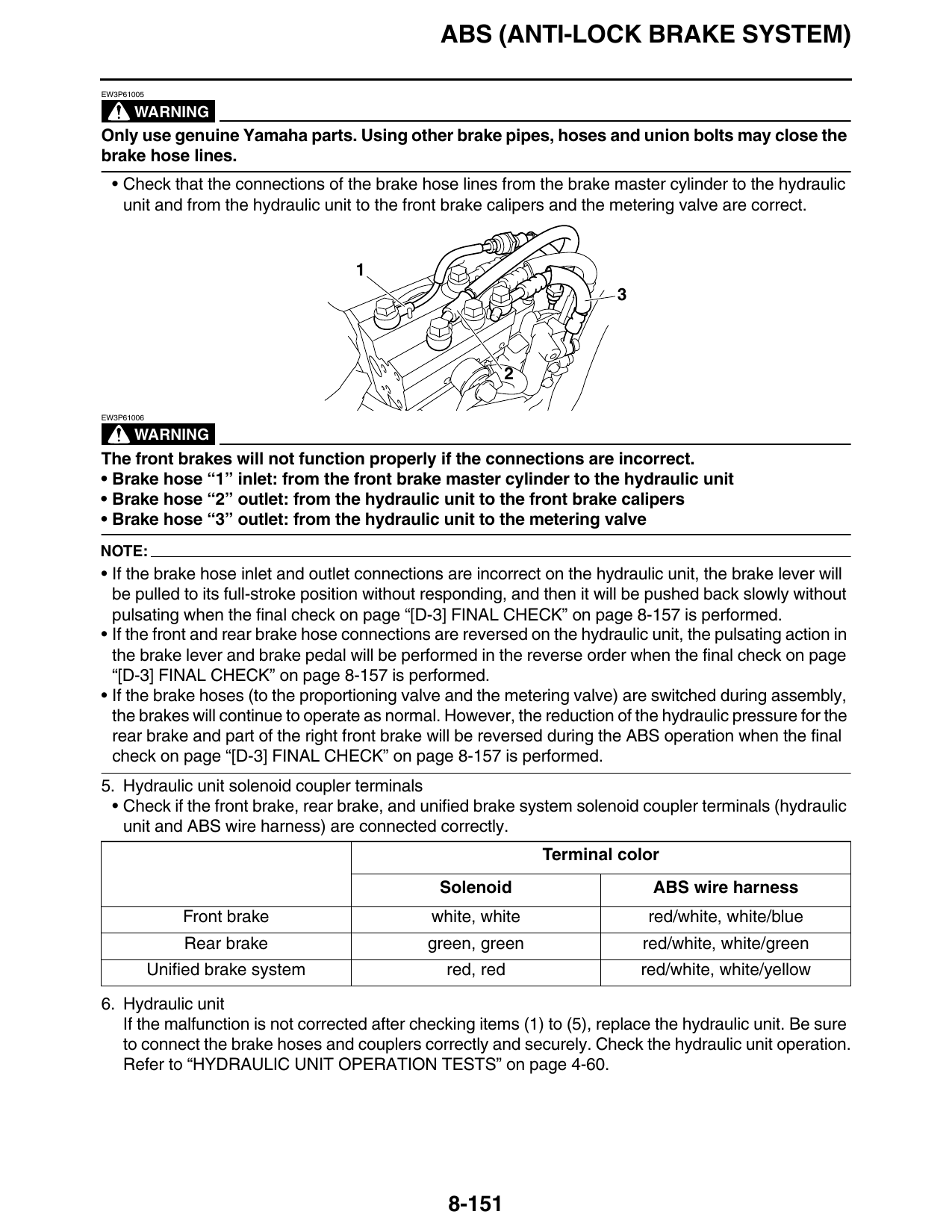
• Check that the connections of the brake hose lines from the brake master cylinder to the hydraulic
unit and from the hydraulic unit to the front brake calipers and the metering valve are correct.
EW3P61006
WARNING
The front brakes will not function properly if the connections are incorrect.
• Brake hose “1” inlet: from the front brake master cylinder to the hydraulic unit
• Brake hose “2” outlet: from the hydraulic unit to the front brake calipers
• Brake hose “3” outlet: from the hydraulic unit to the metering valve
NOTE:
• If the brake hose inlet and outlet connections are incorrect on the hydraulic unit, the brake lever will
be pulled to its full-stroke position without responding, and then it will be pushed back slowly without
pulsating when the final check on page “[D-3] FINAL CHECK” on page 8-157 is performed.
• If the front and rear brake hose connections are reversed on the hydraulic unit, the pulsating action in
the brake lever and brake pedal will be performed in the reverse order when the final check on page
“[D-3] FINAL CHECK” on page 8-157 is performed.
• If the brake hoses (to the proportioning valve and the metering valve) are switched during assembly,
the brakes will continue to operate as normal. However, the reduction of the hydraulic pressure for the
rear brake and part of the right front brake will be reversed during the ABS operation when the final
check on page “[D-3] FINAL CHECK” on page 8-157 is performed.
5. Hydraulic unit solenoid coupler terminals
• Check if the front brake, rear brake, and unified brake system solenoid coupler terminals (hydraulic
unit and ABS wire harness) are connected correctly.
Terminal color
Solenoid ABS wire harness
Front brake white, white red/white, white/blue
Rear brake green, green red/white, white/green
Unified brake system red, red red/white, white/yellow
6. Hydraulic unit
If the malfunction is not corrected after checking items (1) to (5), replace the hydraulic unit. Be sure
to connect the brake hoses and couplers correctly and securely. Check the hydraulic unit operation.
Refer to “HYDRAULIC UNIT OPERATION TESTS” on page 4-60.
8-151
ABS (ANTI-LOCK BRAKE SYSTEM)
Malfunction code 42 (Rear wheel will not recover from the locking tendency even though the
signal is continuously transmitted from the ABS ECU to release the hydraulic pressure (when
the battery voltage is normal).)
1. Rotation of wheel
• Check that there is no brake disc drag on the rear wheel and make sure that it rotates smoothly.
• Check for brake disc distortion.
2. Brake master cylinder and brake caliper
• Check that the brake fluid pressure is correctly transmitted to the brake caliper when the brake pedal
is operated and that the pressure decreases when the pedal is released.
3. Brake fluid
• Visually check the brake fluid in the brake fluid reservoir for water, foreign materials, solidification,
and contamination.
• Check for air in the brake hose lines.
4. Brake hose lines
• Check the brake hose lines for kinks and deterioration (particularly between the hydraulic unit and
the rear brake caliper).
EW3P61005
WARNING
Only use genuine Yamaha parts. Using other brake pipes, hoses and union bolts may close the
brake hose lines.
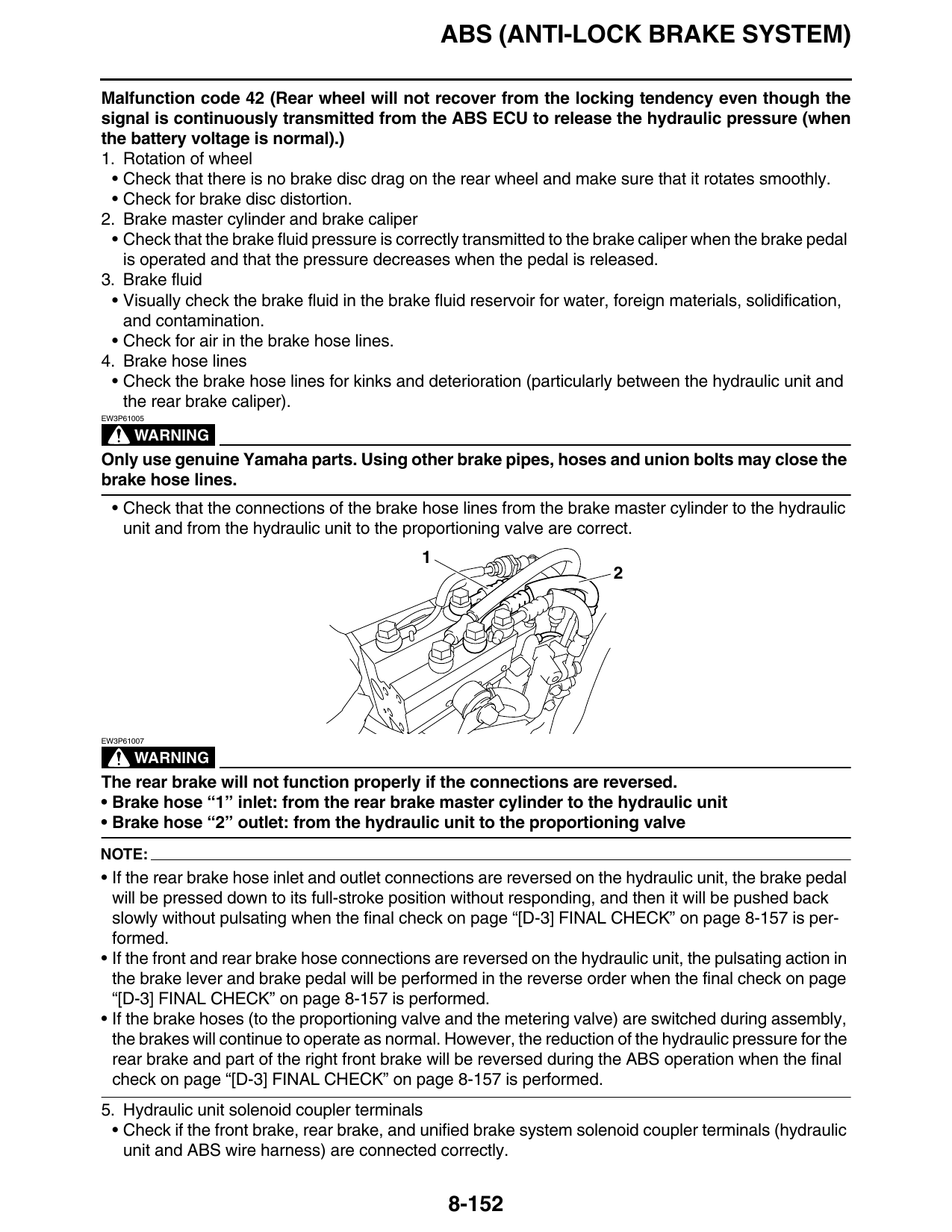
• Check that the connections of the brake hose lines from the brake master cylinder to the hydraulic
unit and from the hydraulic unit to the proportioning valve are correct.
EW3P61007
WARNING
The rear brake will not function properly if the connections are reversed.
• Brake hose “1” inlet: from the rear brake master cylinder to the hydraulic unit
• Brake hose “2” outlet: from the hydraulic unit to the proportioning valve
NOTE:
• If the rear brake hose inlet and outlet connections are reversed on the hydraulic unit, the brake pedal
will be pressed down to its full-stroke position without responding, and then it will be pushed back
slowly without pulsating when the final check on page “[D-3] FINAL CHECK” on page 8-157 is per-
formed.
• If the front and rear brake hose connections are reversed on the hydraulic unit, the pulsating action in
the brake lever and brake pedal will be performed in the reverse order when the final check on page
“[D-3] FINAL CHECK” on page 8-157 is performed.
• If the brake hoses (to the proportioning valve and the metering valve) are switched during assembly,
the brakes will continue to operate as normal. However, the reduction of the hydraulic pressure for the
rear brake and part of the right front brake will be reversed during the ABS operation when the final
check on page “[D-3] FINAL CHECK” on page 8-157 is performed.
5. Hydraulic unit solenoid coupler terminals
• Check if the front brake, rear brake, and unified brake system solenoid coupler terminals (hydraulic
unit and ABS wire harness) are connected correctly.
8-152
ABS (ANTI-LOCK BRAKE SYSTEM)
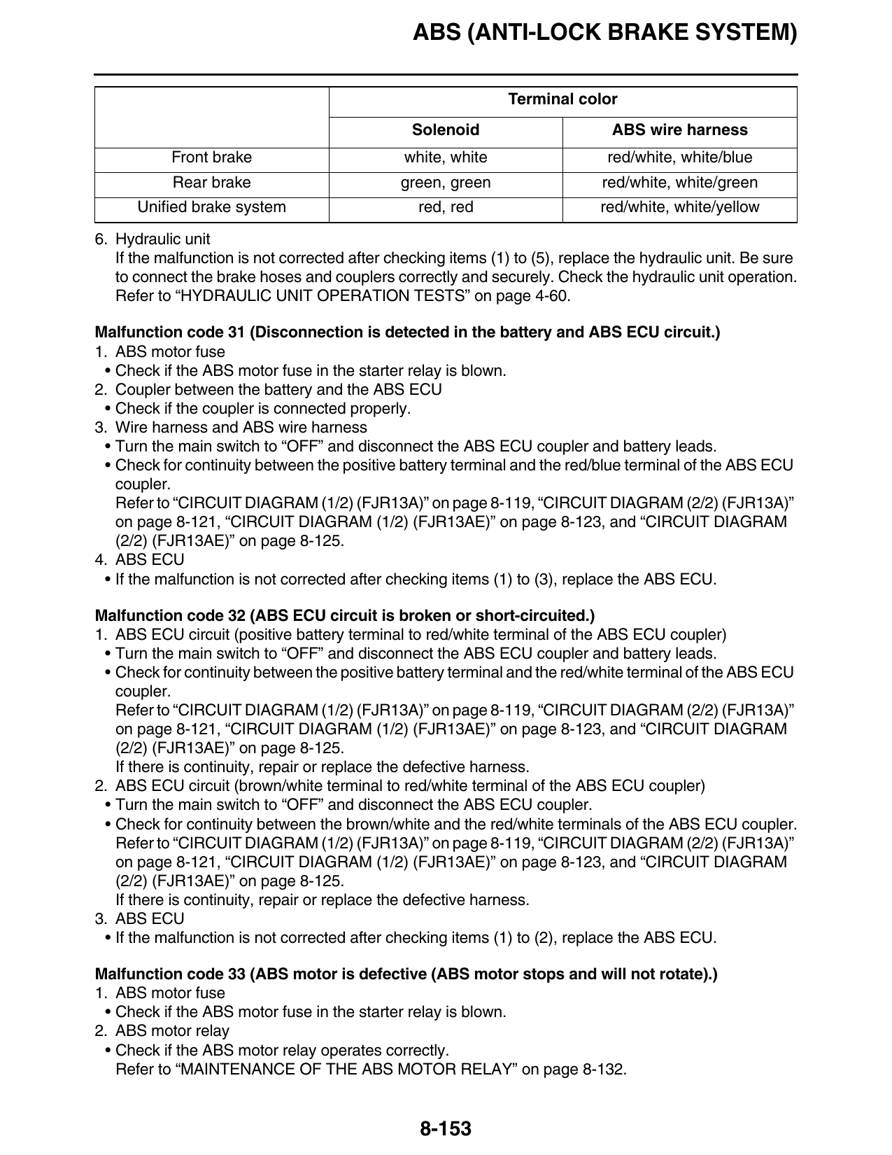
Terminal color
Solenoid ABS wire harness
Front brake white, white red/white, white/blue
Rear brake green, green red/white, white/green
Unified brake system red, red red/white, white/yellow
6. Hydraulic unit
If the malfunction is not corrected after checking items (1) to (5), replace the hydraulic unit. Be sure
to connect the brake hoses and couplers correctly and securely. Check the hydraulic unit operation.
Refer to “HYDRAULIC UNIT OPERATION TESTS” on page 4-60.
Malfunction code 31 (Disconnection is detected in the battery and ABS ECU circuit.)
1. ABS motor fuse
• Check if the ABS motor fuse in the starter relay is blown.
2. Coupler between the battery and the ABS ECU
• Check if the coupler is connected properly.
3. Wire harness and ABS wire harness
• Turn the main switch to “OFF” and disconnect the ABS ECU coupler and battery leads.
• Check for continuity between the positive battery terminal and the red/blue terminal of the ABS ECU
coupler.
Refer to “CIRCUIT DIAGRAM (1/2) (FJR13A)” on page 8-119, “CIRCUIT DIAGRAM (2/2) (FJR13A)”
on page 8-121, “CIRCUIT DIAGRAM (1/2) (FJR13AE)” on page 8-123, and “CIRCUIT DIAGRAM
(2/2) (FJR13AE)” on page 8-125.
4. ABS ECU
• If the malfunction is not corrected after checking items (1) to (3), replace the ABS ECU.
Malfunction code 32 (ABS ECU circuit is broken or short-circuited.)
1. ABS ECU circuit (positive battery terminal to red/white terminal of the ABS ECU coupler)
• Turn the main switch to “OFF” and disconnect the ABS ECU coupler and battery leads.
• Check for continuity between the positive battery terminal and the red/white terminal of the ABS ECU
coupler.
Refer to “CIRCUIT DIAGRAM (1/2) (FJR13A)” on page 8-119, “CIRCUIT DIAGRAM (2/2) (FJR13A)”
on page 8-121, “CIRCUIT DIAGRAM (1/2) (FJR13AE)” on page 8-123, and “CIRCUIT DIAGRAM
(2/2) (FJR13AE)” on page 8-125.
If there is continuity, repair or replace the defective harness.
2. ABS ECU circuit (brown/white terminal to red/white terminal of the ABS ECU coupler)
• Turn the main switch to “OFF” and disconnect the ABS ECU coupler.
• Check for continuity between the brown/white and the red/white terminals of the ABS ECU coupler.
Refer to “CIRCUIT DIAGRAM (1/2) (FJR13A)” on page 8-119, “CIRCUIT DIAGRAM (2/2) (FJR13A)”
on page 8-121, “CIRCUIT DIAGRAM (1/2) (FJR13AE)” on page 8-123, and “CIRCUIT DIAGRAM
(2/2) (FJR13AE)” on page 8-125.
If there is continuity, repair or replace the defective harness.
3. ABS ECU
• If the malfunction is not corrected after checking items (1) to (2), replace the ABS ECU.
Malfunction code 33 (ABS motor is defective (ABS motor stops and will not rotate).)
1. ABS motor fuse
• Check if the ABS motor fuse in the starter relay is blown.
2. ABS motor relay
• Check if the ABS motor relay operates correctly.
Refer to “MAINTENANCE OF THE ABS MOTOR RELAY” on page 8-132.
8-153
ABS (ANTI-LOCK BRAKE SYSTEM)
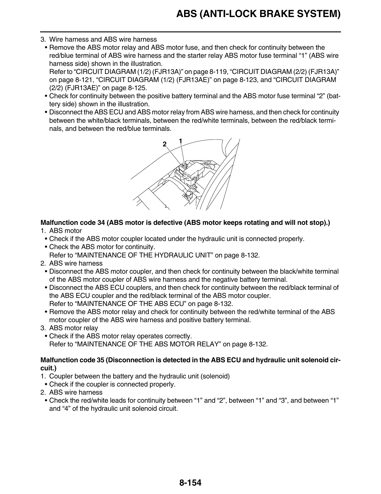
3. Wire harness and ABS wire harness
• Remove the ABS motor relay and ABS motor fuse, and then check for continuity between the
red/blue terminal of ABS wire harness and the starter relay ABS motor fuse terminal “1” (ABS wire
harness side) shown in the illustration.
Refer to “CIRCUIT DIAGRAM (1/2) (FJR13A)” on page 8-119, “CIRCUIT DIAGRAM (2/2) (FJR13A)”
on page 8-121, “CIRCUIT DIAGRAM (1/2) (FJR13AE)” on page 8-123, and “CIRCUIT DIAGRAM
(2/2) (FJR13AE)” on page 8-125.
• Check for continuity between the positive battery terminal and the ABS motor fuse terminal “2” (bat-
tery side) shown in the illustration.
• Disconnect the ABS ECU and ABS motor relay from ABS wire harness, and then check for continuity
between the white/black terminals, between the red/white terminals, between the red/black termi-
nals, and between the red/blue terminals.
2 1
Malfunction code 34 (ABS motor is defective (ABS motor keeps rotating and will not stop).)
1. ABS motor
• Check if the ABS motor coupler located under the hydraulic unit is connected properly.
• Check the ABS motor for continuity.
Refer to “MAINTENANCE OF THE HYDRAULIC UNIT” on page 8-132.
2. ABS wire harness
• Disconnect the ABS motor coupler, and then check for continuity between the black/white terminal
of the ABS motor coupler of ABS wire harness and the negative battery terminal.
• Disconnect the ABS ECU couplers, and then check for continuity between the red/black terminal of
the ABS ECU coupler and the red/black terminal of the ABS motor coupler.
Refer to “MAINTENANCE OF THE ABS ECU” on page 8-132.
• Remove the ABS motor relay and check for continuity between the red/white terminal of the ABS
motor coupler of the ABS wire harness and positive battery terminal.
3. ABS motor relay
• Check if the ABS motor relay operates correctly.
Refer to “MAINTENANCE OF THE ABS MOTOR RELAY” on page 8-132.
Malfunction code 35 (Disconnection is detected in the ABS ECU and hydraulic unit solenoid cir-
cuit.)
1. Coupler between the battery and the hydraulic unit (solenoid)
• Check if the coupler is connected properly.
2. ABS wire harness
• Check the red/white leads for continuity between “1” and “2”, between “1” and “3”, and between “1”
and “4” of the hydraulic unit solenoid circuit.
8-154