🏍️ FJR1300 RP13

Checking The Fuses

Fragment manuala — str. 688

📋 Tekst do skopiowania / wyszukiwania
ELECTRICAL COMPONENTS

                                                     NOTE:
                                                     Set the pocket tester selector to “Ω × 1”.

                                                                  Pocket tester
                                                                   90890-03112
                                                                  Analog pocket tester
                                                                   YU-03112-C

                                                     b. If the pocket tester indicates “∞”, replace the
                                                        fuse.
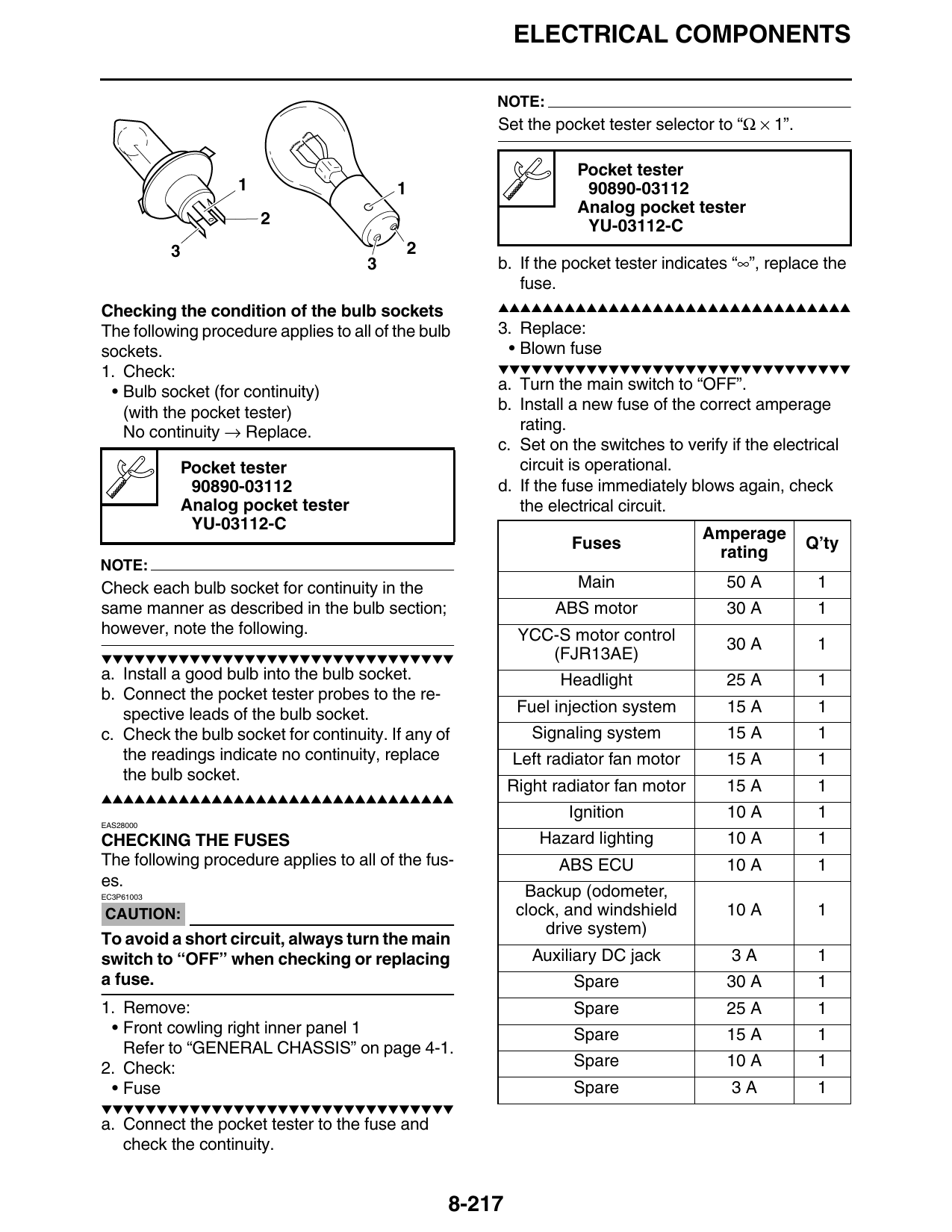
Checking the condition of the bulb sockets           ▲▲▲▲▲▲▲▲▲▲▲▲▲▲▲▲▲▲▲▲▲▲▲▲▲▲▲▲▲▲▲▲
The following procedure applies to all of the bulb   3. Replace:
sockets.                                              • Blown fuse
1. Check:                                            ▼▼▼▼▼▼▼▼▼▼▼▼▼▼▼▼▼▼▼▼▼▼▼▼▼▼▼▼▼▼▼▼
 • Bulb socket (for continuity)                      a. Turn the main switch to “OFF”.
   (with the pocket tester)                          b. Install a new fuse of the correct amperage
   No continuity → Replace.                             rating.
                                                     c. Set on the switches to verify if the electrical
            Pocket tester                               circuit is operational.
             90890-03112                             d. If the fuse immediately blows again, check
            Analog pocket tester                        the electrical circuit.
             YU-03112-C
                                                                                    Amperage
                                                                 Fuses                            Q’ty
                                                                                     rating
NOTE:
Check each bulb socket for continuity in the                      Main                50 A         1
same manner as described in the bulb section;                  ABS motor              30 A         1
however, note the following.                              YCC-S motor control
                                                                                      30 A         1
▼▼▼▼▼▼▼▼▼▼▼▼▼▼▼▼▼▼▼▼▼▼▼▼▼▼▼▼▼▼▼▼                             (FJR13AE)
a. Install a good bulb into the bulb socket.                    Headlight             25 A         1
b. Connect the pocket tester probes to the re-
   spective leads of the bulb socket.                     Fuel injection system       15 A         1
c. Check the bulb socket for continuity. If any of          Signaling system          15 A         1
   the readings indicate no continuity, replace          Left radiator fan motor      15 A         1
   the bulb socket.
                                                         Right radiator fan motor     15 A         1
▲▲▲▲▲▲▲▲▲▲▲▲▲▲▲▲▲▲▲▲▲▲▲▲▲▲▲▲▲▲▲▲
                                                                 Ignition             10 A         1
EAS28000

CHECKING THE FUSES                                           Hazard lighting          10 A         1
The following procedure applies to all of the fus-             ABS ECU                10 A         1
es.
EC3P61003                                                  Backup (odometer,
CAUTION:                                                  clock, and windshield       10 A         1
                                                              drive system)
To avoid a short circuit, always turn the main
switch to “OFF” when checking or replacing                  Auxiliary DC jack          3A          1
a fuse.                                                          Spare                30 A         1
1. Remove:                                                       Spare                25 A         1
 • Front cowling right inner panel 1                             Spare                15 A         1
   Refer to “GENERAL CHASSIS” on page 4-1.
2. Check:                                                        Spare                10 A         1
 • Fuse                                                          Spare                 3A          1
▼▼▼▼▼▼▼▼▼▼▼▼▼▼▼▼▼▼▼▼▼▼▼▼▼▼▼▼▼▼▼▼
a. Connect the pocket tester to the fuse and
   check the continuity.

                                                 8-217