Checking The Rectifier/Regulator
Fragment manuala — str. 700
📋 Tekst do skopiowania / wyszukiwania
ELECTRICAL COMPONENTS
EAS28180
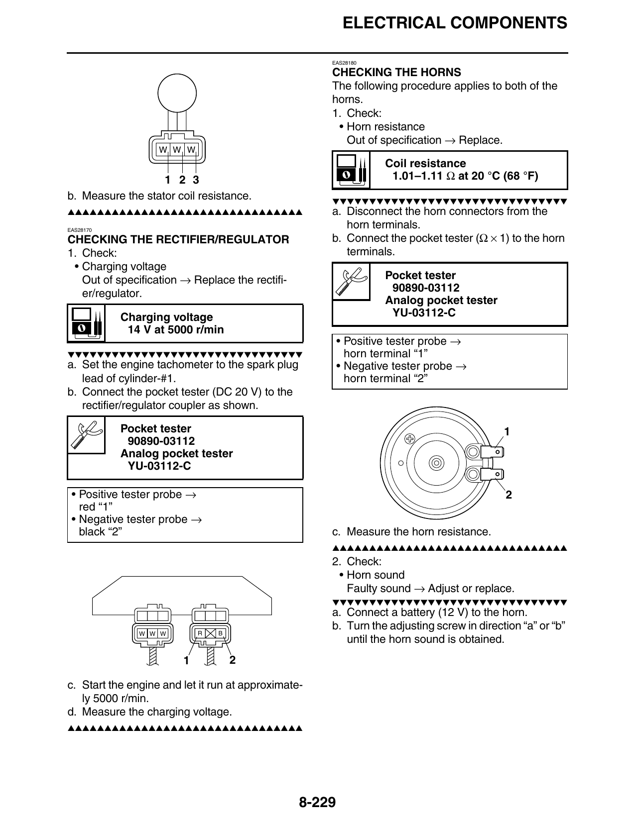
CHECKING THE HORNS
The following procedure applies to both of the
horns.
1. Check:
• Horn resistance
Out of specification → Replace.
W W W
Coil resistance
1 2 3 1.01–1.11 Ω at 20 °C (68 °F)
b. Measure the stator coil resistance. ▼▼▼▼▼▼▼▼▼▼▼▼▼▼▼▼▼▼▼▼▼▼▼▼▼▼▼▼▼▼▼▼
▲▲▲▲▲▲▲▲▲▲▲▲▲▲▲▲▲▲▲▲▲▲▲▲▲▲▲▲▲▲▲▲ a. Disconnect the horn connectors from the
EAS28170
horn terminals.
CHECKING THE RECTIFIER/REGULATOR b. Connect the pocket tester (Ω × 1) to the horn
1. Check: terminals.
• Charging voltage
Out of specification → Replace the rectifi- Pocket tester
er/regulator. 90890-03112
Analog pocket tester
Charging voltage YU-03112-C
14 V at 5000 r/min
• Positive tester probe →
▼▼▼▼▼▼▼▼▼▼▼▼▼▼▼▼▼▼▼▼▼▼▼▼▼▼▼▼▼▼▼▼ horn terminal “1”
a. Set the engine tachometer to the spark plug • Negative tester probe →
lead of cylinder-#1. horn terminal “2”
b. Connect the pocket tester (DC 20 V) to the
rectifier/regulator coupler as shown.
Pocket tester 1
90890-03112
Analog pocket tester
YU-03112-C
• Positive tester probe → 2
red “1”
• Negative tester probe →
black “2” c. Measure the horn resistance.
▲▲▲▲▲▲▲▲▲▲▲▲▲▲▲▲▲▲▲▲▲▲▲▲▲▲▲▲▲▲▲▲
2. Check:
• Horn sound
Faulty sound → Adjust or replace.
▼▼▼▼▼▼▼▼▼▼▼▼▼▼▼▼▼▼▼▼▼▼▼▼▼▼▼▼▼▼▼▼
a. Connect a battery (12 V) to the horn.
b. Turn the adjusting screw in direction “a” or “b”
W W W R B
until the horn sound is obtained.
1 2
c. Start the engine and let it run at approximate-
ly 5000 r/min.
d. Measure the charging voltage.
▲▲▲▲▲▲▲▲▲▲▲▲▲▲▲▲▲▲▲▲▲▲▲▲▲▲▲▲▲▲▲▲
8-229