Checking The Stator Coil
Fragment manuala — str. 699
📋 Tekst do skopiowania / wyszukiwania
ELECTRICAL COMPONENTS
Pocket tester
90890-03112
Analog pocket tester
YU-03112-C
• Positive tester probe →
yellow/green “1”
• Negative tester probe →
black/blue “2”
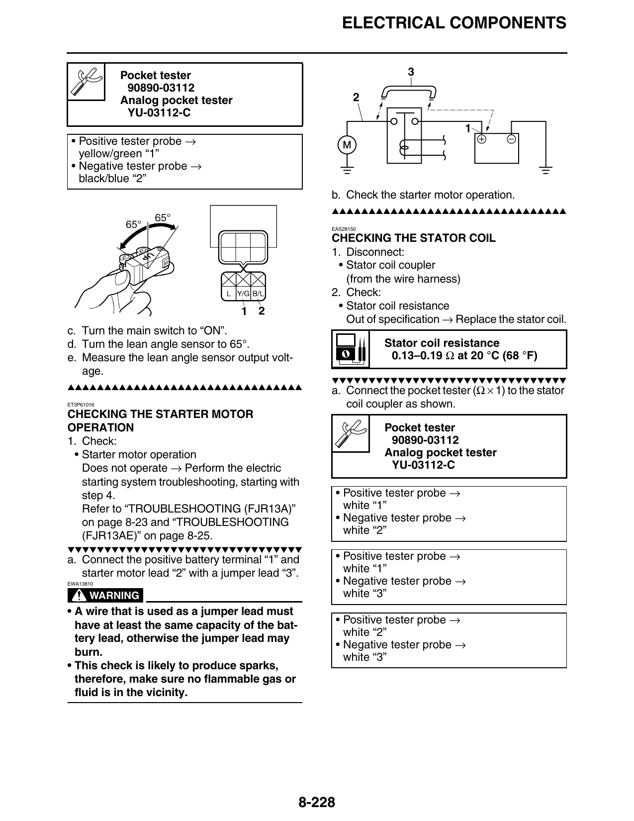
b. Check the starter motor operation.
▲▲▲▲▲▲▲▲▲▲▲▲▲▲▲▲▲▲▲▲▲▲▲▲▲▲▲▲▲▲▲▲
EAS28150
CHECKING THE STATOR COIL
1. Disconnect:
• Stator coil coupler
(from the wire harness)
2. Check:
• Stator coil resistance
Out of specification → Replace the stator coil.
c. Turn the main switch to “ON”.
d. Turn the lean angle sensor to 65°. Stator coil resistance
e. Measure the lean angle sensor output volt- 0.13–0.19 Ω at 20 °C (68 °F)
age.
▼▼▼▼▼▼▼▼▼▼▼▼▼▼▼▼▼▼▼▼▼▼▼▼▼▼▼▼▼▼▼▼
▲▲▲▲▲▲▲▲▲▲▲▲▲▲▲▲▲▲▲▲▲▲▲▲▲▲▲▲▲▲▲▲
a. Connect the pocket tester (Ω × 1) to the stator
ET3P61016 coil coupler as shown.
CHECKING THE STARTER MOTOR
OPERATION Pocket tester
1. Check: 90890-03112
• Starter motor operation Analog pocket tester
Does not operate → Perform the electric YU-03112-C
starting system troubleshooting, starting with
step 4. • Positive tester probe →
Refer to “TROUBLESHOOTING (FJR13A)” white “1”
on page 8-23 and “TROUBLESHOOTING • Negative tester probe →
(FJR13AE)” on page 8-25. white “2”
▼▼▼▼▼▼▼▼▼▼▼▼▼▼▼▼▼▼▼▼▼▼▼▼▼▼▼▼▼▼▼▼
a. Connect the positive battery terminal “1” and • Positive tester probe →
starter motor lead “2” with a jumper lead “3”. white “1”
EWA13810 • Negative tester probe →
WARNING white “3”
• A wire that is used as a jumper lead must
have at least the same capacity of the bat- • Positive tester probe →
white “2”
tery lead, otherwise the jumper lead may
• Negative tester probe →
burn. white “3”
• This check is likely to produce sparks,
therefore, make sure no flammable gas or
fluid is in the vicinity.
8-228