🏍️ FJR1300 RP13

Checking The Relay Unit (Diode)

Fragment manuala — str. 696

📋 Tekst do skopiowania / wyszukiwania
ELECTRICAL COMPONENTS

                                                                Continuity
                                                                 Positive tester probe → sky blue
                                                                 “1”
                                                                 Negative tester probe →
                                                                 black/yellow “2”
                                                                No continuity
                                                                 Positive tester probe →
                                                                 black/yellow “2”
                                                                 Negative tester probe → sky
                                                                 blue “1”
b. Turn the main switch to “ON”.                                Continuity
c. Measure the turn signal/hazard relay output                   Positive tester probe → sky blue
   voltage.                                                      “1”
▲▲▲▲▲▲▲▲▲▲▲▲▲▲▲▲▲▲▲▲▲▲▲▲▲▲▲▲▲▲▲▲                                 Negative tester probe →
EAS28050
                                                                 black/red “3”
CHECKING THE RELAY UNIT (DIODE)                                 No continuity
1. Check:                                                        Positive tester probe →
 • Relay unit (diode)                                            black/red “3”
                                                                 Negative tester probe → sky
   Out of specification → Replace.
                                                                 blue “1”
           Pocket tester                                        Continuity
            90890-03112                                          Positive tester probe → sky blue
           Analog pocket tester                                  “1”
            YU-03112-C                                           Negative tester probe → sky
                                                                 blue/white “4”
                                                                No continuity
NOTE:                                                            Positive tester probe → sky
The pocket tester and the analog pocket tester                   blue/white “4”
readings are shown in the following table.                       Negative tester probe → sky
                                                                 blue “1”
                                                                Continuity
                                                                 Positive tester probe →
                                                                 blue/green “5”
                                                                 Negative tester probe →
                                                                 black/red “3”
                                                                No continuity
                                                                 Positive tester probe →
                                                                 black/red “3”
                                                                 Negative tester probe →
                                                                 blue/green “5”

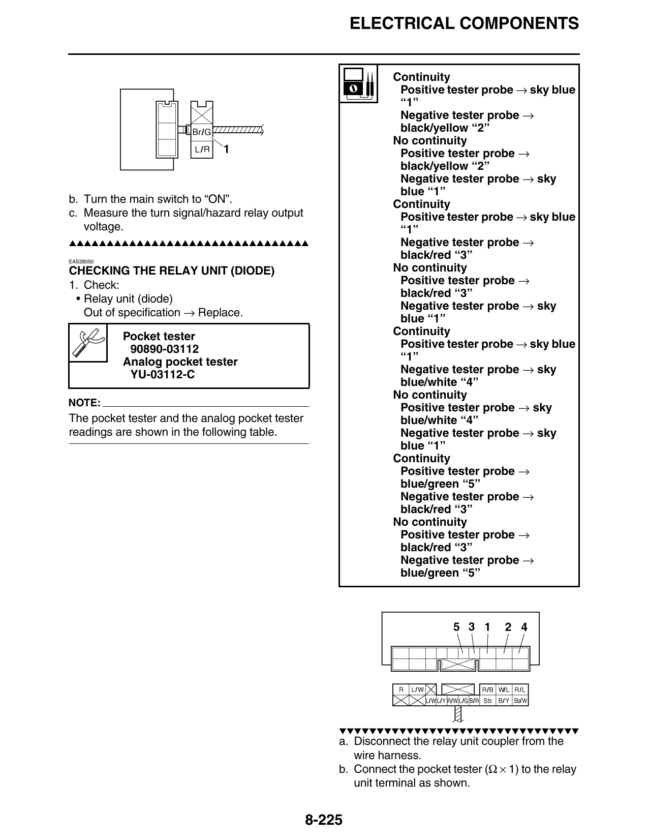
                                                     ▼▼▼▼▼▼▼▼▼▼▼▼▼▼▼▼▼▼▼▼▼▼▼▼▼▼▼▼▼▼▼▼
                                                     a. Disconnect the relay unit coupler from the
                                                        wire harness.
                                                     b. Connect the pocket tester (Ω × 1) to the relay
                                                        unit terminal as shown.

                                                 8-225