Checking The Turn Signal/Hazard Relay
Fragment manuala — str. 695
📋 Tekst do skopiowania / wyszukiwania
ELECTRICAL COMPONENTS
Pocket tester
90890-03112
Analog pocket tester
YU-03112-C
2 1
• Positive tester probe →
W/B R/W
blue/red “1”
R /B
• Negative tester probe →
R /L
ground
▲▲▲▲▲▲▲▲▲▲▲▲▲▲▲▲▲▲▲▲▲▲▲▲▲▲▲▲▲▲▲▲
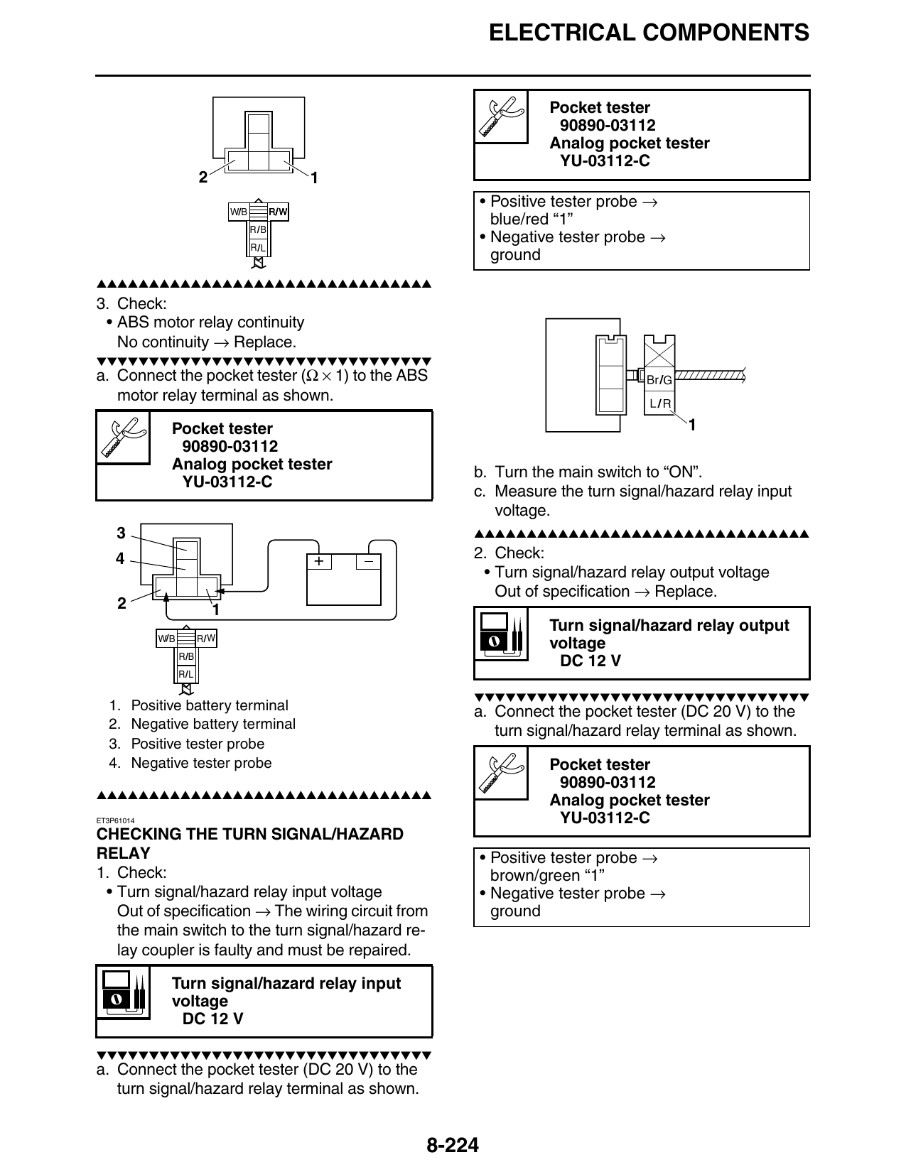
3. Check:
• ABS motor relay continuity
No continuity → Replace.
▼▼▼▼▼▼▼▼▼▼▼▼▼▼▼▼▼▼▼▼▼▼▼▼▼▼▼▼▼▼▼▼
a. Connect the pocket tester (Ω × 1) to the ABS
motor relay terminal as shown.
Pocket tester
90890-03112
Analog pocket tester b. Turn the main switch to “ON”.
YU-03112-C
c. Measure the turn signal/hazard relay input
voltage.
3 ▲▲▲▲▲▲▲▲▲▲▲▲▲▲▲▲▲▲▲▲▲▲▲▲▲▲▲▲▲▲▲▲
4 + 2. Check:
• Turn signal/hazard relay output voltage
Out of specification → Replace.
2 1
Turn signal/hazard relay output
W/B R/W
voltage
R/B
DC 12 V
R/L
▼▼▼▼▼▼▼▼▼▼▼▼▼▼▼▼▼▼▼▼▼▼▼▼▼▼▼▼▼▼▼▼
1. Positive battery terminal a. Connect the pocket tester (DC 20 V) to the
2. Negative battery terminal turn signal/hazard relay terminal as shown.
3. Positive tester probe
4. Negative tester probe Pocket tester
90890-03112
▲▲▲▲▲▲▲▲▲▲▲▲▲▲▲▲▲▲▲▲▲▲▲▲▲▲▲▲▲▲▲▲ Analog pocket tester
ET3P61014 YU-03112-C
CHECKING THE TURN SIGNAL/HAZARD
RELAY • Positive tester probe →
1. Check: brown/green “1”
• Turn signal/hazard relay input voltage • Negative tester probe →
Out of specification → The wiring circuit from ground
the main switch to the turn signal/hazard re-
lay coupler is faulty and must be repaired.
Turn signal/hazard relay input
voltage
DC 12 V
▼▼▼▼▼▼▼▼▼▼▼▼▼▼▼▼▼▼▼▼▼▼▼▼▼▼▼▼▼▼▼▼
a. Connect the pocket tester (DC 20 V) to the
turn signal/hazard relay terminal as shown.
8-224