Checking The Throttle Position Sensor
Fragment manuala — str. 703
📋 Tekst do skopiowania / wyszukiwania
ELECTRICAL COMPONENTS
EAS28370
Coolant temperature sensor CHECKING THE AIR INDUCTION SYSTEM
T.
R.
18 Nm (1.8 m·kg, 13 ft·lb) SOLENOID
1. Check:
EAS28300 • Air induction system solenoid resistance
CHECKING THE THROTTLE POSITION Out of specification → Replace.
SENSOR
1. Remove: Solenoid resistance
• Throttle position sensor 19–25 Ω at 20 °C (68 °F)
(from the throttle body)
▼▼▼▼▼▼▼▼▼▼▼▼▼▼▼▼▼▼▼▼▼▼▼▼▼▼▼▼▼▼▼▼
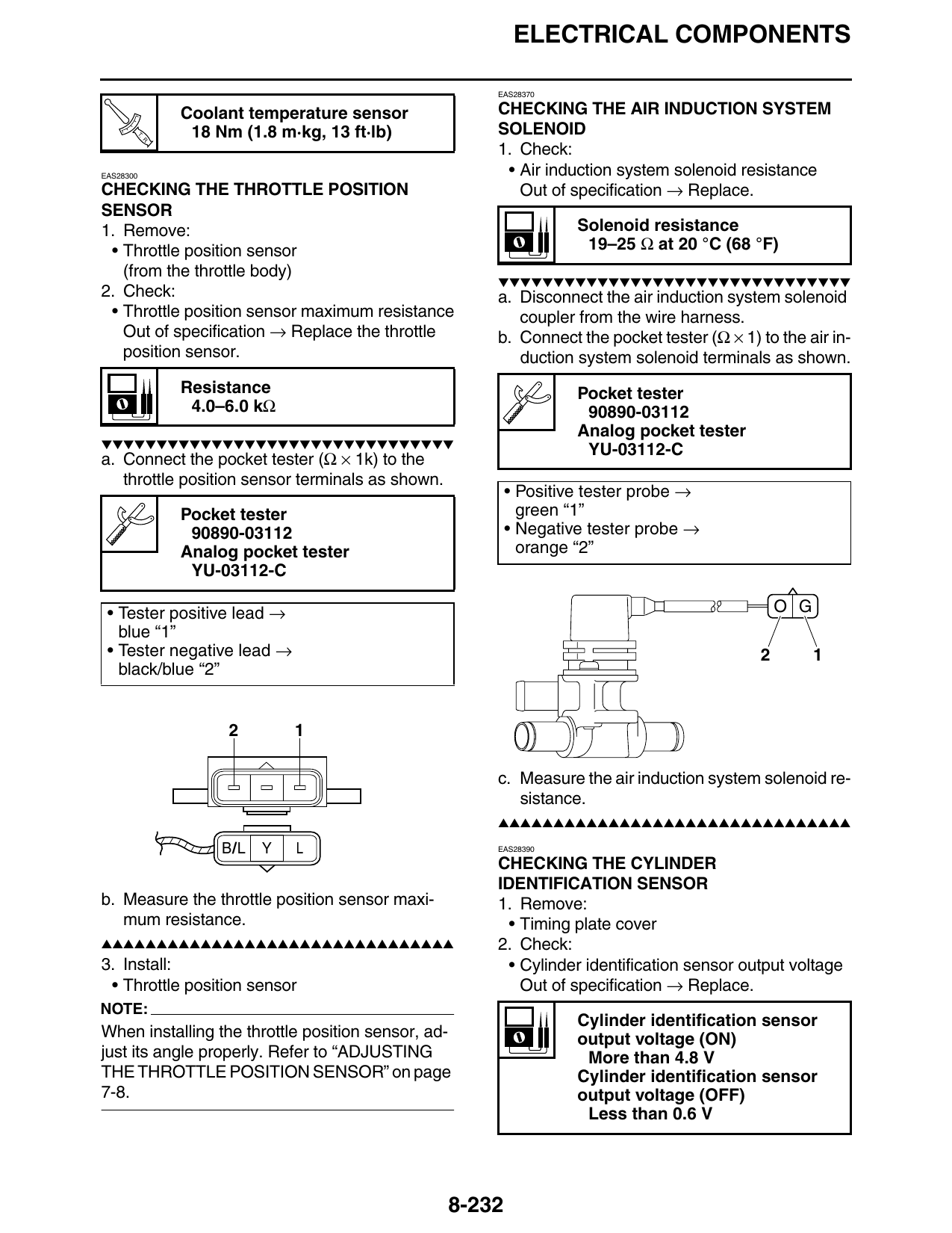
2. Check: a. Disconnect the air induction system solenoid
• Throttle position sensor maximum resistance coupler from the wire harness.
Out of specification → Replace the throttle b. Connect the pocket tester (Ω × 1) to the air in-
position sensor. duction system solenoid terminals as shown.
Resistance Pocket tester
4.0–6.0 kΩ 90890-03112
Analog pocket tester
▼▼▼▼▼▼▼▼▼▼▼▼▼▼▼▼▼▼▼▼▼▼▼▼▼▼▼▼▼▼▼▼
YU-03112-C
a. Connect the pocket tester (Ω × 1k) to the
throttle position sensor terminals as shown.
• Positive tester probe →
Pocket tester green “1”
90890-03112 • Negative tester probe →
Analog pocket tester orange “2”
YU-03112-C
• Tester positive lead → O G
blue “1”
• Tester negative lead → 2 1
black/blue “2”
2 1
c. Measure the air induction system solenoid re-
sistance.
▲▲▲▲▲▲▲▲▲▲▲▲▲▲▲▲▲▲▲▲▲▲▲▲▲▲▲▲▲▲▲▲
B/L Y L EAS28390
CHECKING THE CYLINDER
IDENTIFICATION SENSOR
b. Measure the throttle position sensor maxi- 1. Remove:
mum resistance. • Timing plate cover
▲▲▲▲▲▲▲▲▲▲▲▲▲▲▲▲▲▲▲▲▲▲▲▲▲▲▲▲▲▲▲▲ 2. Check:
3. Install: • Cylinder identification sensor output voltage
• Throttle position sensor Out of specification → Replace.
NOTE:
Cylinder identification sensor
When installing the throttle position sensor, ad- output voltage (ON)
just its angle properly. Refer to “ADJUSTING More than 4.8 V
THE THROTTLE POSITION SENSOR” on page Cylinder identification sensor
7-8. output voltage (OFF)
Less than 0.6 V
8-232