[D-3] Final Check
Fragment manuala — str. 628–629
📋 Tekst do skopiowania / wyszukiwania
ABS (ANTI-LOCK BRAKE SYSTEM)
▼▼▼▼▼▼▼▼▼▼▼▼▼▼▼▼▼▼▼▼▼▼▼▼▼▼▼▼▼▼▼▼
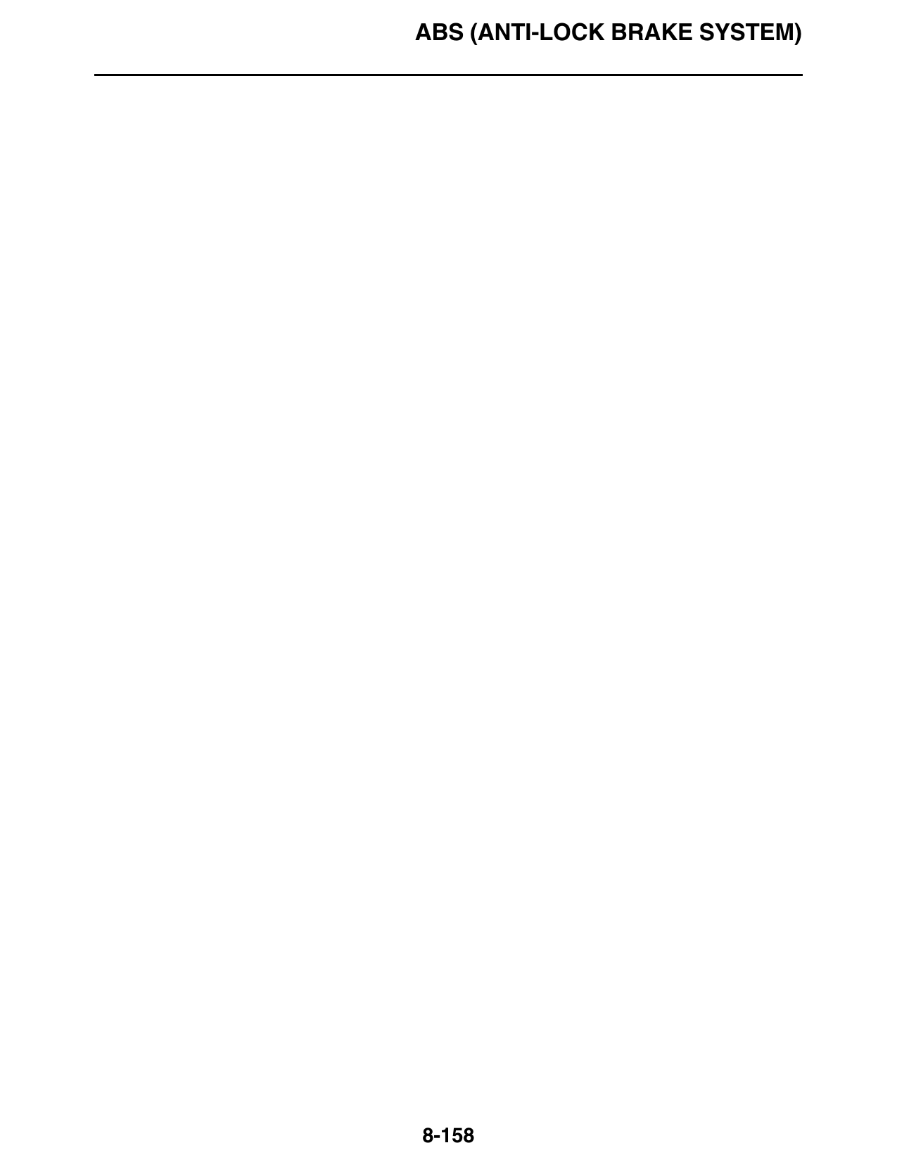
Pocket tester a. Connect the pocket tester (DC 12 V) to the
90890-03112 ABS ECU couplers.
Analog pocket tester
YU-03112-C Pocket tester
90890-03112
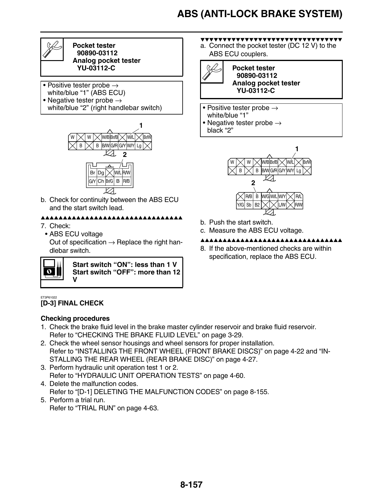
• Positive tester probe → Analog pocket tester
white/blue “1” (ABS ECU) YU-03112-C
• Negative tester probe →
white/blue “2” (right handlebar switch) • Positive tester probe →
white/blue “1”
1 • Negative tester probe →
black “2”
W W W/B Br/B W/L Br/W
B B B/W G/R G/Y W/Y Lg
W W W/B Br/B W/L Br/W
Br Dg W/L R/W B B B/W G/R G/Y W/Y Lg
G/Y Ch Br/G B R/B 2
R/B B W/G W/L W/Y R/L
b. Check for continuity between the ABS ECU
Y/G Sb B2 L/W R/W
and the start switch lead.
▲▲▲▲▲▲▲▲▲▲▲▲▲▲▲▲▲▲▲▲▲▲▲▲▲▲▲▲▲▲▲▲
b. Push the start switch.
7. Check:
c. Measure the ABS ECU voltage.
• ABS ECU voltage
▲▲▲▲▲▲▲▲▲▲▲▲▲▲▲▲▲▲▲▲▲▲▲▲▲▲▲▲▲▲▲▲
Out of specification → Replace the right han-
dlebar switch. 8. If the above-mentioned checks are within
specification, replace the ABS ECU.
Start switch “ON”: less than 1 V
Start switch “OFF”: more than 12
V
ET3P61022
[D-3] FINAL CHECK
Checking procedures
1. Check the brake fluid level in the brake master cylinder reservoir and brake fluid reservoir.
Refer to “CHECKING THE BRAKE FLUID LEVEL” on page 3-29.
2. Check the wheel sensor housings and wheel sensors for proper installation.
Refer to “INSTALLING THE FRONT WHEEL (FRONT BRAKE DISCS)” on page 4-22 and “IN-
STALLING THE REAR WHEEL (REAR BRAKE DISC)” on page 4-27.
3. Perform hydraulic unit operation test 1 or 2.
Refer to “HYDRAULIC UNIT OPERATION TESTS” on page 4-60.
4. Delete the malfunction codes.
Refer to “[D-1] DELETING THE MALFUNCTION CODES” on page 8-155.
5. Perform a trial run.
Refer to “TRIAL RUN” on page 4-63.
8-157
ABS (ANTI-LOCK BRAKE SYSTEM)
8-158